AUBER INSTRUMENTS
WWW.AUBERINS.COM
2017.01
P2/5
C.1 Description of Wiring Terminals (T1 ~ T14)
T1: the circuit ground pole for input signals.
T2: for TC, mA, and mV signals in Channel 1 (use withT1).
T3: for TC, mA, and mV signals in Channel 2 (use withT1)
T4: for RTD signal in Channel 1 (use withT1 and T2).
T5: for RTD signal in Channel 2 (use withT1 and T3).
T6: for the positive side of 12V DC power.
T7: for the negative side of 12V DC power.
T8: for +12V DC illumination signal from headlight (use with T7).
T9: a 5V DC power for pressure sensor (use with T13/T14 and T1).
T10: the common pole for J1 and J2 relay.
T11: output for J2 (normally open) relay (use with T10).
T12: output for J1 (normally open) relay (use with T10).
T13: for pressure sensor in Channel 1 (use with T9 and T1).
T14: for pressure sensor in Channel 2 (use with T9 and T1).
Please see Table 2 for a summary for terminal assignment.
Table 2. Summary of Terminal Assignments.
Terminal Description Channel
Use
With
T1
Circuit Ground (all input sensors)
1 & 2
T2
TC1, mA1, mV1
1
T1
T3
TC2, mA2, mV2
2
T1
T4
RTD1
1
T1 & T2
T5
RTD2
2
T1 & T3
T6
+12V DC power
T7
T7
-12V DC power
T6
T8
Headlight 12V DC
T7
T9
5V DC output for pressure sensor
1 & 2
T10
Common pole for relays
1 & 2
T11
Output for J2 relay
T10
T12
Output for J1 relay
T10
T13
Pressure sensor 1 (voltage signal)
1
T9 & T1
T14
Pressure sensor 2 (voltage signal)
2
T9 & T1
C.2 General Wiring Rules
1. T6 and T7 are 12 VDC power input for the controller.
2. T1-T5, T13, and T14 are for different types of input signals. T1 is the circuit
ground for all input signals.
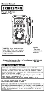
3. Wiring of Thermocouples (TC). For Channel 1, connect the positive side of
the TC to T2, the negative side to T1. For Channel 2, connect the positive side
of the TC to T3, the negative side to T1. (See Figure 4(a).)
4. Wiring of Resistance Temperature Detectors (RTD). In Channel 1, for a
three wire RTD, connect the two red wires to T1 and T2, connect white wire to
T4; for a two wire RTD, connect the red wire to T2, and connect the white wire
to T4, and short T1 and T2. In Channel 2, for a three wire RTD, connect the
two red wires to T1 and T3, connect white wire to T5; for a two wire RTD,
connect the red wire to T3, and connect the white wire to T5, and short T3 and
T1. (See Figure 4(b).)
5. Wiring of Pressure Sensors. In Channel 1, connect the power source wire of
the sensor to T9, the signal wire of the sensor to T13, and the ground wire of
the sensor to T1. In Channel 2, connect the power source wire of the sensor to
T9, the signal wire of the sensor to T14, and the ground wire of the sensor to
T1. (See Figure 4(c).)
6. Wiring of mV and mA signals. Wiring for these signals are similar to
thermocouple sensors.
7. T8 is for display brightness control. When connecting the illumination signal
(+12 VDC) to it, the brightness with synchronized with headlight. If not
connected, the brightness can still be controlled by UP key “
Λ
”. Use T8 and T7.
8. Wiring for relay output. J1 and J2 are two normally open relays. T10 is a
common pole for both relays. Use T12 and T10 for J1 relay. Use T11 and T10
for J2 relay. (See Figure 4(d).)
(a) (b)
(c) (d)
Figure 4. Wiring diagram for (a) thermocouples, (b) RTDs, (c) pressure sensors, and (d)
relays.
D. Parameter Settings
D.1 Basic Parameters (
Press SET key then enter 0089 to enter setting mode)
D.1.a) Basic Parameters
The gauge SYL-2813 has two input channels that can read signals from two
different sensors simultaneously. Each channel can have its own input sensor
type, specified scale range, and input offset. See Table 3 for a list of basic
parameters, description, range, and initial values. A list of valid types of input
sensor is given in Table 4. Please note that all 19 input types are available for
Channel 1, but the last three input types in Table 3, i.e., 0 - 10 mA, 0 - 20 mA,
and 4 - 20 mA, are not available for Channel 2.
Table 3. Basic Parameters.
Symbol Name
Description
Channel Range Initial Note
Int1
Int1
Input type of Channel 1
1
See Table 3
P100
1
Dot1
dot1
Decimal Point Position 1
0000 ~ 0.000
0
2
Pul1
PuL1
Scale Low 1
-1999 ~ 9999
1000
3
Puh1
PuH1
Scale High 1
-1999 ~ 9999
2000
6
7
8
9
10
14
13
12
11
1
2
3
4
5
SYL-28 13
R
RTD2
RTD1
Ground
R
R
R
W
W
6
7
8
9
10
14
13
12
11
1
2
3
4
5
SYL-28 13
−
+
+
TC2
TC1
6
7
8
9
10
14
13
12
11
1
2
3
4
5
SYL-28 13
Pr
es
su
re
S
en
so
r 1
Pr
ess
ur
e S
en
so
r 2
5V pow er
Ground
6
7
8
9
10
14
13
12
11
1
2
3
4
5
SYL-28 13
DC 12V
+
−
Common
Buzze r
(controlled by
J1 rela y)