koban KMD-S04, Manual
The koban KMD-S04 is a versatile device that brings convenience to your daily life. With an intuitive interface, it allows users to effortlessly navigate its features. To maximize your experience, a comprehensive user manual is available for free download at manualshive.com. Get the most out of your koban KMD-S04 with our detailed manual.
Share
Download


Reviews:
No comments
Related manuals for KMD-S04

1195/8E1
Brand: Patton electronics Pages: 12

22-168A
Brand: Radio Shack Pages: 46

FLASHMETER
Brand: HT Italia Pages: 16

320 Series
Brand: IDEAL Pages: 20

KEW MATE 2000A
Brand: KYORITSU Pages: 3

72-10395
Brand: Tenma Pages: 8

SK-350
Brand: Kaise Pages: 16

T8211D
Brand: CABAC Pages: 10

BM821
Brand: CABAC Pages: 23

MS8233A
Brand: Mastech Pages: 8

25302
Brand: Maxwell Digital Multimeters Pages: 24

25331
Brand: Maxwell Digital Multimeters Pages: 32
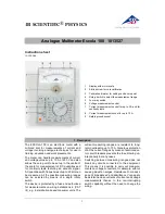
Escola 100
Brand: 3B SCIENTIFIC Pages: 8

MT832
Brand: Major tech Pages: 12

GDT-311
Brand: GB Pages: 2

7074
Brand: Keithley Pages: 109
6160
Brand: Cisco Pages: 20

6160
Brand: Cisco Pages: 38


