


CHAPTER 4: INSTALLATION
4-8
MDU Solutions
®
– DVIS/DVISm - Digital Video Insertion System & Mini Digital Video Insertion System - Installation & Operation Manual
“Connecting to the Management Computer” on page 5-5
“Connecting to a Local Cable Modem” on page 5-5
The Ethernet port is DTE, similar to a PC Ethernet port and will require a crossover cable to connect to a PC. Connection to a
router or switch may be made with a standard straight through cable. Port speed is 10/100 Base-T and will auto negotiate the
connection based on the fastest common speed of the DVIS Device and connected equipment.
4.10.2 Ethernet Cable Type
Connect DVIS to:
Router or Switch
Computer
Cable Type
Straight Through
Crossover
Cables of high quality meeting Cat5e or Cat6 are recommended. A crossover cable is supplied with every DVIS unit.
4.11 Installing Modules
For information on removing or installing modules, see
“15. Module Field Replacement” on page 15-1
4.12 Cable Management Bar
The cable management bar may be used to
organize and provide strain relief to cables entering
the cabinet. Be careful to not over tighten cable
ties to avoid distorting the coaxial cables which
could result in return loss discontinuities.
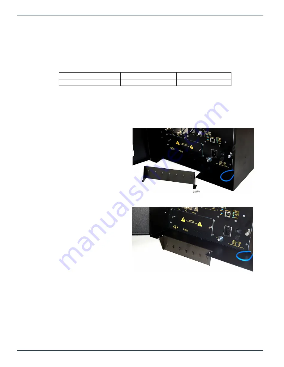
4.12.1 Moving the Cable Management Bar
The cable management bar can be mounted to the
exterior of the cabinet to facilitate removal of the
power supply. To mount the cable bar below the
unit:
1. Remove the four pan head Phillips
screws from the under side of the cabinet
bottom panel.
2. Remove the cable bar, see Figure 4-6.
3. Position the cable bar facing downwards
underneath the unit.
4. Fasten the cable bar into place on the
cabinet bottom panel using the four
4.12.2 Power Supply Access
As shipped, the cable management bar blocks access to the power supply. This is not an issue unless, in the unlikely event,
the power supply needs to be changed. It is up to the installer as to which position of the cable bar best suits the installation.
Figure 4-6:
Cable Management Bar Removed
Figure 4-7:
Cable Management Bar Inverted Outward


