Page 49
© 2001-2015 attocube systems AG. Product and company names listed are trademarks or trade names of their respective
companies. Any rights not expressly granted herein are reserved. ATTENTION: Specifications and technical data are subject
to change without notice.
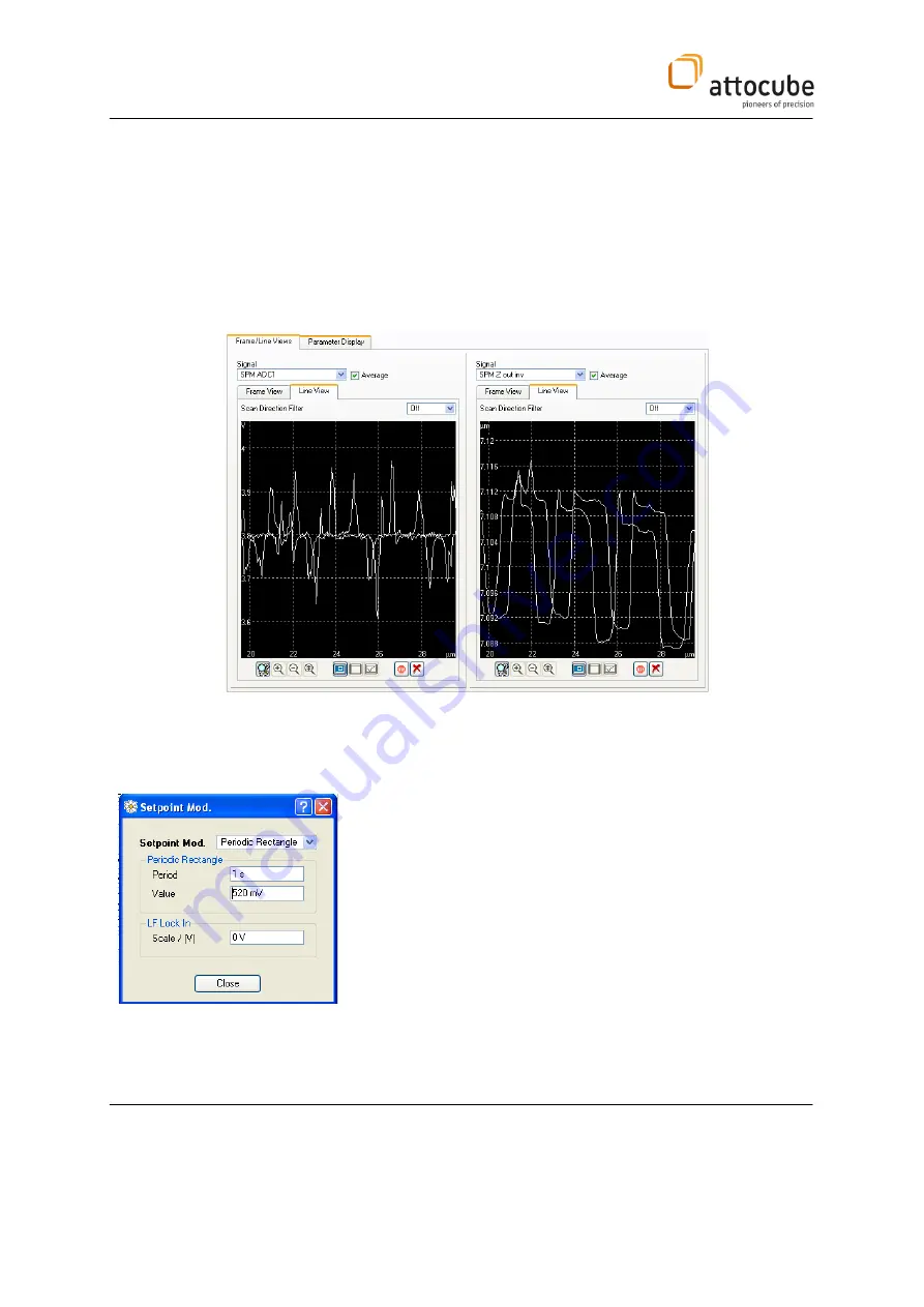
Normally, in contact mode ‘ADC1’ (error signal) and the ‘SPM Z out inv’
(topography signal) is recorded.
In non-contact mode ‘AFM Aosc’ (error signal) and the ‘SPM Z out inv’
(topography signal) is recorded.
During scanning, the P and I parameters of the feedback loop have to be
adjusted according to the chosen scan speed and the surface roughness. At
the same scan speed, for example, a rougher surface will need a faster
feedback loop compared to a smooth surface.
In addition, the sample tilt can be compensated by setting a proper slope
compensation value for x and y. This feature can also be found in the
‘Feedback’ box.
Choosing P, I parameters:
To find reasonable start values for the P, I parameters, a 'Setpoint
Modulation' can be used. This feature is found in the 'Feedback’ box. As
parameters choose:
Setpoint Mod.: Periodic Rectangle
Period:
1s
Value:
95% or 105% of current setpoint
Start the feedback. The setpoint modulation will simulate a step-like pattern
on the sample surface. You can choose P and I for minimum response time
without overshoot (increase P and/or I) or lower noise.
Now, a scan may be started.
Содержание attoAFM I
Страница 20: ...Page 20 III 5 Changing the AFM Cantilever...


