www.atlona.com | toll free:
1-877-536-3976
For International: 1-
408-962-0515
8
Dip Switch Settings
DS1
DS2
DS3
DS4
CAT5 Output Connection and EDID
0
0
0
0
Auto EDID and Copy EDID
1
0
0
0
Dual CAT5, 1080p, 2ch audio
1
0
0
1
Single CAT5, 1080p, 2ch audio
1
0
1
0
Dual CAT5, 1080p, 5.1ch audio
1
0
1
1
Single CAT5, 1080p, 5.1ch audio
1
1
0
0
Dual CAT5, 1080p, 7.1ch audio
1
1
0
1
Single CAT5, 1080p, 7.1ch audio
1
1
1
0
Dual CAT5, 1080i, 2ch audio
1
1
1
1
Single CAT5, 1080i, 2ch audio
C). Copy EDID: Please set the dip switch to “0000” (off). Make sure to
power cycle
the AT-PROHD85M-SR
after making this setting change on the dip switch. Turn off power and then back on to complete a power cycle.
-
play that you want to copy and then the source input. Next press and hold the previously selected output and
F/N button simultaneously for a couple of seconds then release. Characters on the LED display will rotate in
a circular pattern until process is complete. If EDID successfully copied the LED will display “M OK”. If unsuc-
cessful it will display “M FL”. Repeat process for all desired input/output associations.
Note: If you wish to return the copied EDID back to the auto EDID functionality use the following steps.
Step 1: Set the dip switch to 1-1-1-1(on), next power cycle the AT-PROHD85M-SR.
Step 2: Set the dip switch to 0-0-0-0(off), next power cycle the AT-PROHD85M-SR. All connected devices will
be reset to the lowest common denominator.
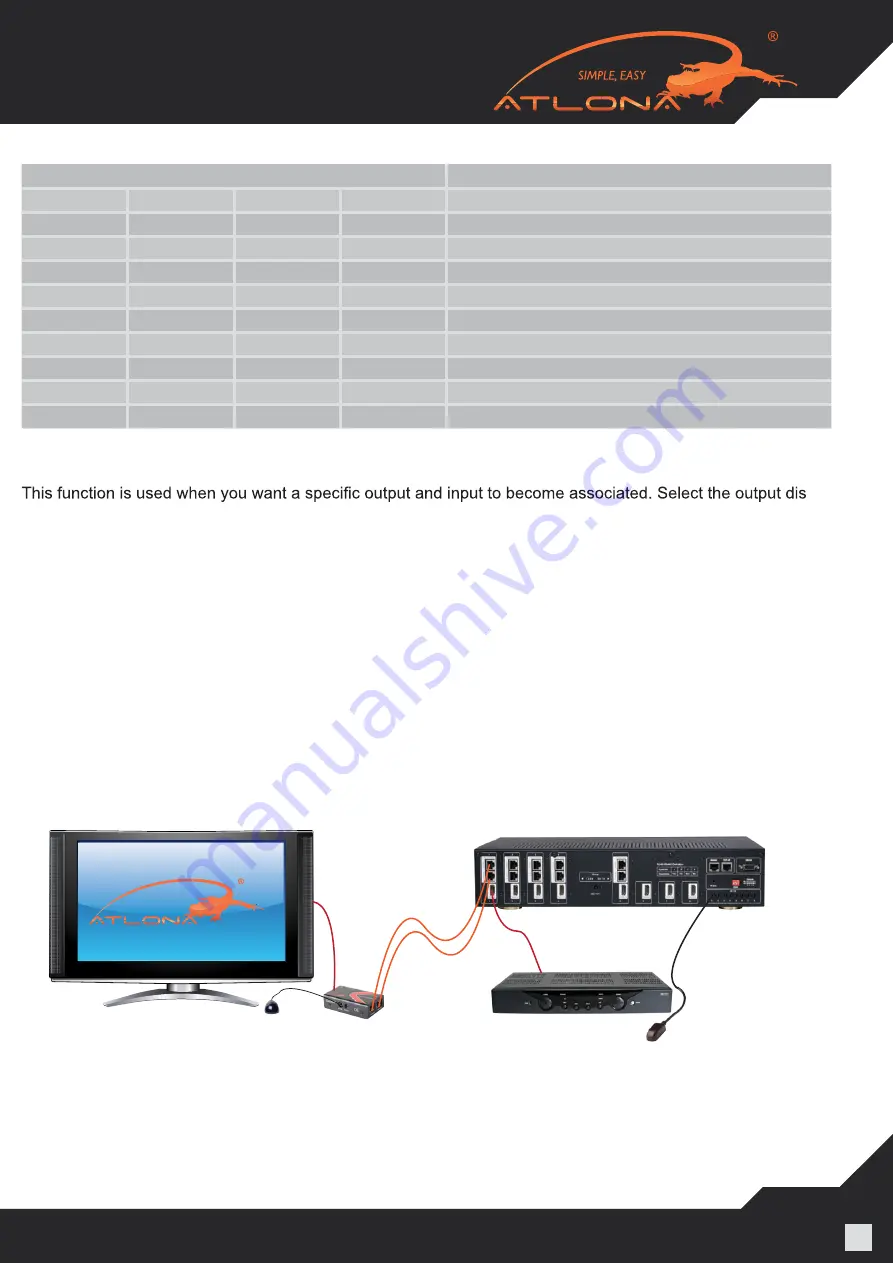
4. Connect supplied IR
receiver
and
emitter
cables
to the AT-PROHD85M-SR
and supplied matrix receivers for IR
functionality
. T
rans
mitters need to be placed over IR window on device to
ensure successful functionality. IR
receiver modules
should
be placed in line of sight for handheld controller to
successfully extend IR commands.
Note: When connecting IR receivers and IR emitters be extremely careful to insert them into the correct port.
Failure to do so will cause damage to the switch, receiver or burn out the IR eye.
5. If you wish to control the AT-PROHD85M-SR from a 3rd party control system connect an RS-232 cable
between the matrix and the control system.
Please use a straight RS-232 Cable
for this connection .
(View RS232 codes on page 12)
7. For computer control connect a RJ45 cable to the TCP/IP port of the AT-PROHD85M-SR.
Note: If the TCP/IP port is connected directly to a computer you must use a crossover CAT5 cable. If connect-
ed to a router use a straight wire CAT5 cable.
RX
TX


