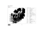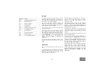
- 23 -
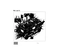
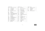
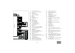
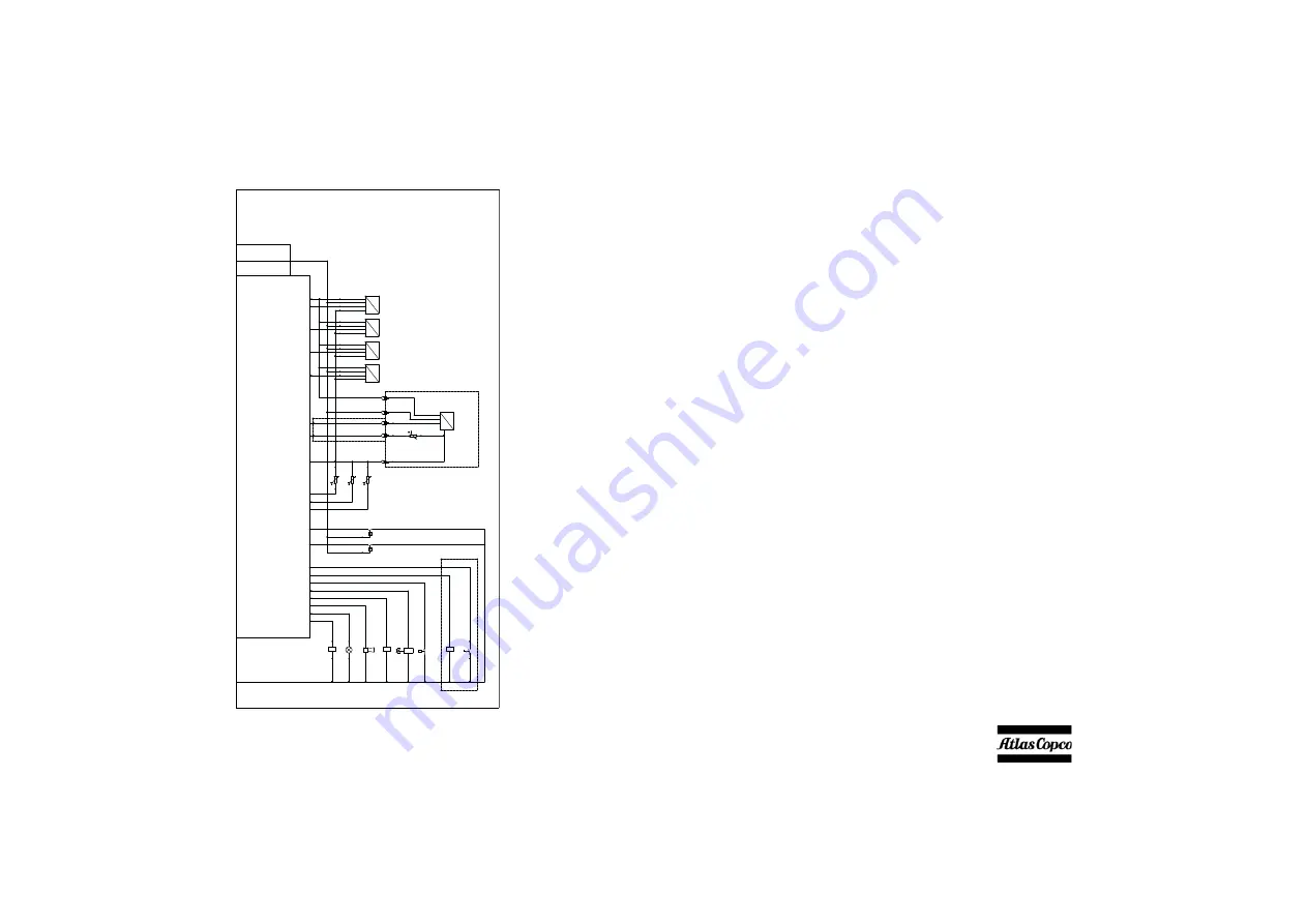
C1
Spare I/O (female contacts)
C2
CAT engine service tool connector
F1
Fuse 15A
F2
Fuse 15A, roof
F3
Fuse 15A, preheater
F4
Fuse 15A, internal lights
G1
Battery
G2
Battery
G3
Alternator
H4
Warning flasher light
H6
Horn
H7-H10 Internal lights
K0
Relay, Starter motor
K1
Relay, Aux. starter
K2
Relay, Roof actuator
K3
Relay, Refuelling pump
K4
Relay, Refinary equipment
K5
Relay, Ether start
K6
Timer relay
K7
Relay
LS1
Level Switch, Coolant level Warning
LS2
Level Switch, Coolant level Shutdown
LT1
Level sensor, Fuel level
M1
Starter motor
M2
Roof actuator
N1
Compressor Control Module
N2
Engine Control Module (Caterpillar)
N3
Roof actuator controller
N4
Hydronic heater
N5
Timer
N6
Receiver wireless remote control
N7
Compressor control module remote connector
P1
Refuelling pump
P2
Fuel pump preheater
PS1
Pressure Switch, Airfilter
PT1
Pressure sensor, Vessel pressure
PT2
Pressure sensor, Regulating Pressure
PT3
Pressure sensor, Interstage pressure
PT4
Pressure sensor, Aftercooler
R1
Resistor 470 Ohm 3W
R2
Termination resistor 120 Ohm
S1
Emergency Stop
S2
Battery switch
S3
Fuel supply selector switch
S4
Dual pressure selector switch
S5
Internal lights switch
TT1
Temperature sensor, PT1000, LP Element
temperature
TT2
Temperature sensor, PT1000, HP element
temperature
TT3
Temperature sensor, PT1000, Ambient
temperature
TT4
Temperature sensor, PT1000, Aftercooler
Y1
Loading Valve
Y2 Blow-off
valve
Y3
Air shut-off valve
Y4 Dual
pressure
valve
X1
Optional equipment
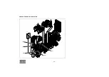
1
Fused 24 VDC for Spare I/O’s and options
2
24 VDC (power supply box) for Spare I/O’s and
options
3
Fused 24 VDC for Spare I/O’s and options
4
Fused 24 VDC after Emergency Stop for Spare
I/O’s and options
5
5 VDC for Spare I/O’s and options
6
Power After Contact for Spare I/O’s and options
7
Digital Ground for Spare I/O’s and options
8
Switched Ground for Spare I/O’s and options
9
Unswitched Ground
10
Switched Ground (power supply box) for Spare
I/O’s and options
11
Switched Ground for Spare I/O’s and options
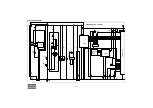
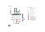
X1
C1
18
18
ADS-T
ADS-P
28
29
TT4
T-IN 06
PT4
V-
SIG
V+ 5VDC
V+ 24VDC
U
P
X1
1
19 85
86
K1
45
19 85
86
K3
19
19
28
31
34
28
LS1
LS2
44
44
19 85
86
K2
19
19
37
37
19
S3
15
15
LT1
SIG
V-
V+ 5VDC
V+ 24VDC
U
L
28
29
18
PT3
SIG
V-
V+ 5VDC
V+ 24VDC
U
P
PT2
SIG
V-
V+ 5VDC
V+ 24VDC
U
P
PT1
28
29
18
28
29
18
28
29
32
33
33
32
H6
H4
C10
B6
C15
A15
B4
C6
D15
D16
B9
B7
D9
C9
A7
B16
A3
A4
C16
A1
D7
B8
C8
B3
19
30
2
2
31
34
30
19
P
PS1
Y1
1
11
10
9
6
6
11
18
TT3
4
5
5
10
9
4
18
29
18
18
V-IN 06
24M
SIG
V-
V+ 5VDC
V+ 24VDC
U
P
TT2
TT1
5
6
7
CONTROLLER
Содержание XRVS 1300 CD7
Страница 2: ......
Страница 20: ... 20 PNEUMATIC REGULATING SYSTEM AR RV CEhp CElp BOV TV UA ...
Страница 32: ... 32 ENTER button Confirms stores the selection change BACK button Moves back one level or ignores the change ...
Страница 95: ...Dataplate 95 ...
Страница 99: ... 99 Maintenance Log Compressor Customer Serial number Service hours Maintenance action Date By initials ...
Страница 100: ... 100 ...
Страница 101: ......
Страница 102: ......


