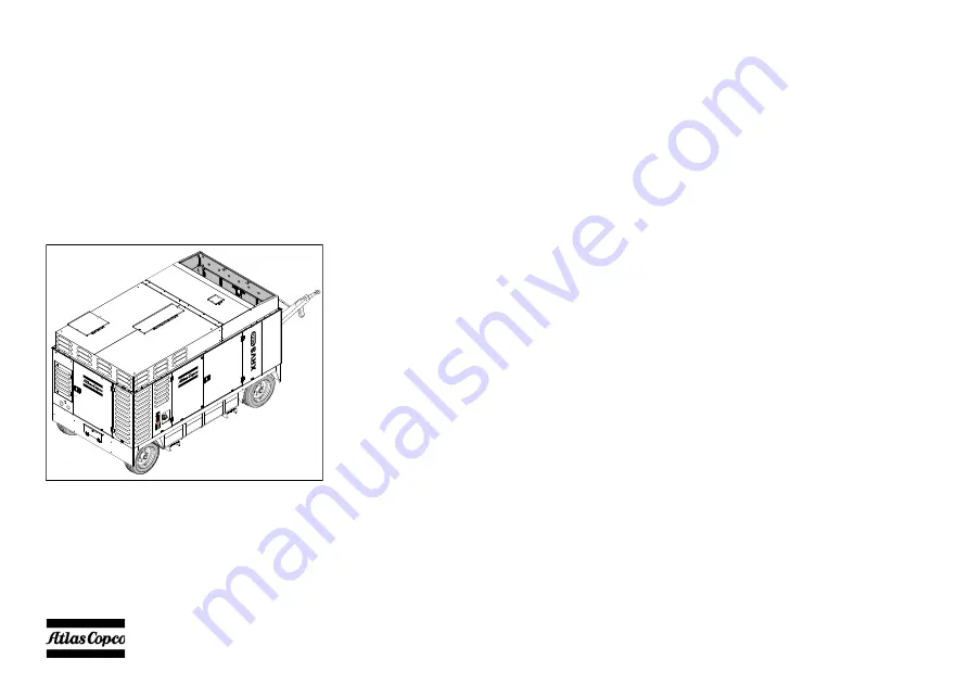
background image

- 14 -

Leading particulars

GENERAL DESCRIPTION

The XRHS 527 Cd - XRHS 1150 CD4 is a silenced,

two-stage, oil-injected screw compressor, built for a

nominal effective working pressure of 20 bar

(290 psi).
The XRVS 487 Cd  - XRVS 1050 CD4 is a silenced,

two-stage, oil-injected screw compressor, built for a

nominal effective working pressure of 25 bar

(363 psi).

Engine

The compressors are driven by a 6 cilinder in-line

liquid-cooled diesel engine.
The engine’s power is transmitted to the compressor

element through a heavy-duty coupling.

Compressor

The compressor casing houses two screw-type rotors,

mounted on ball and roller bearings. The male rotor,

driven by the engine, drives the female rotor. The

compressor delivers pulsation-free air.
Injected oil is used for sealing, cooling and

lubricating purposes.

Compressor oil system

The oil is boosted by air pressure. The system has no

oil pump.
The oil is removed from the air, in the air/oil vessel at

first by centrifugal force, secondly through the oil

separator element.
The vessel is provided with an oil level indicator.

Regulation

The compressor is provided with a continuous

pneumatic regulating system and a blow-off valve

which is integrated in the unloader assembly. The

valve is closed during operation by air receiver

pressure and opens by air receiver pressure via the

compressor element when the compressor is stopped.
When the air consumption increases, the air receiver

pressure will decrease and vice versa.
This receiver pressure variation is sensed by the

regulating valve which, by means of control air to the

unloader and an electronic engine speed regulator,

matches the air output to the air consumption. The air

receiver pressure is maintained between the pre-

selected working pressure and the corresponding

unloading pressure.

Содержание XRHS 1150 CD4 C3 WUX

Страница 1: ...XRHS 527 Cd C3 WUX XRHS 1150 CD4 C3 WUX XRVS 487 Cd C3 WUX XRVS 1050 CD4 C3 WUX Instruction Manual for Portable Compressors English Engine CAT C13 ...

Страница 2: ......

Страница 3: ...E ENERGY DIVISION www atlascopco com Printed matter N 9829 3014 99 09 2012 Instruction Manual for Portable Compressors XRHS 527 Cd C3 WUX XRHS 1150 CD4 C3 WUX XRVS 487 Cd C3 WUX XRVS 1050 CD4 C3 WUX Original instructions ...

Страница 4: ...er s approval in writing Neglecting maintenance or making changes to the setup of the machine can result in major hazards including fire risk While every effort has been made to ensure that the information in this manual is correct Atlas Copco does not assume responsibility for possible errors Copyright 2012 Atlas Copco Airpower n v Antwerp Belgium Any unauthorized use or copying of the contents o...

Страница 5: ...and lifting instructions 30 4 1 1 Parking instructions Wagon 30 4 1 2 Towing instructions Wagon 31 4 1 3 Towbar levelling Wagon 31 4 1 4 Lifting instructions 32 4 2 Internal lighting 32 4 3 Preheater option 32 4 3 1 Description heating operation 32 4 3 2 Operations overview 33 4 4 Before starting 34 4 5 Starting Stopping 36 4 5 1 Battery switch 36 4 5 2 Control panel 36 4 5 3 Overview icons 38 4 5...

Страница 6: ...lement and the safety cartridge 78 6 2 4 Air receiver 79 6 2 5 Safety valve 79 6 3 Fuel system 79 6 3 1 Priming instructions 79 6 3 2 Replacing filter elements 80 6 3 3 Cleaning crankcase breather filter 80 6 3 4 Maintenance Quick action fuel couplings 81 6 4 Brake adjustments 82 6 4 1 Brake shoe adjustment 82 6 4 2 Brake adjustment wagon without ABS 83 7 Problem solving 84 7 1 Heater failure 87 7...

Страница 7: ...ponents Skill level 3 Electrical technician An electrical technician is trained and has the same qualifications as both the operator and the mechanical technician In addition the electrical technician may carry out electrical repairs within the various enclosures of the unit This includes work on live electrical components Skill level 4 Specialist from the manufacturer This is a skilled specialist...

Страница 8: ... equipment shall be kept clean i e as free as possible from oil dust or other deposits 7 To prevent an increase in working temperature inspect and clean heat transfer surfaces cooler fins intercoolers water jackets etc regularly See the Maintenance schedule compressor 8 All regulating and safety devices shall be maintained with due care to ensure that they function properly They may not be put out...

Страница 9: ...bilize the unit by placing chocks in front of and or behind the wheels When the tow bar can be positioned vertically the locking device must be applied and kept in good order The unit must always be used parked stored in a non publicly accessible area locked away from access by unauthorized persons 6 To lift heavy parts a hoist of ample capacity tested and approved according to local safety regula...

Страница 10: ...rwise stated in the Atlas Copco Instruction Book AIB Keep fuel away from hot parts such as air outlet pipes or the engine exhaust Do not smoke when fuelling When fuelling from an automatic pump an earthing cable should be connected to the unit to discharge static electricity Never spill nor leave oil fuel coolant or cleansing agent in or around the unit 14 All doors shall be shut during operation ...

Страница 11: ...ts the battery shall be disconnected and removed or the terminals covered by insulating caps On electrically driven units the main switch shall be locked in open position and the fuses shall be taken out A warning sign bearing a legend such as work in progress do not supply voltage shall be attached to the fuse box or main switch 4 Before dismantling any pressurized component the compressor or equ...

Страница 12: ...unction properly 20 Maintenance and repair work should be recorded in an operator s logbook for all machinery Frequency and nature of repairs can reveal unsafe conditions 21 When hot parts have to be handled e g shrink fitting special heat resistant gloves shall be used and if required other body protection shall be applied 22 When using cartridge type breathing filter equipment ascertain that the...

Страница 13: ...e technical specifications Safety reasons prohibit any other applications 3 National legislation requirements with respect to re inspection must be complied with 4 No welding or heat treatment of any kind is permitted to those vessel walls which are exposed to pressure 5 The vessel is provided and may only be used with the required safety equipment such as manometer overpressure control devices sa...

Страница 14: ...ses Compressor oil system The oil is boosted by air pressure The system has no oil pump The oil is removed from the air in the air oil vessel at first by centrifugal force secondly through the oil separator element The vessel is provided with an oil level indicator Regulation The compressor is provided with a continuous pneumatic regulating system and a blow off valve which is integrated in the un...

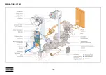
Страница 15: ...as a towbar with parking brakes For available options see chapter Available options Bodywork The bodywork has openings for the intake and outlet of cooling air and hinged doors for maintenance and service operations The bodywork is internally lined with sound absorbing material Lifting beam A lifting beam is accessible when a small door at the top is opened Control panel The control panel grouping...

Страница 16: ... 16 Main parts ...

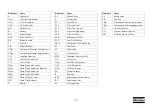
Страница 17: ...in Plug Radiator E Engine Reference Name EP Exhaust Pipe F Cooling Fan FC Fuel Cooler FCf Filler Cap Fuel FCC Filler Cap Coolant FFa Fuel Filter Additional FFf Final Fuel Filter FFp Primary Fuel Filter FLS Fuel Level Sensor FPco Compressor Oil Filling Plug FT Fuel Tank IC Intercooler LV Loading Valve MPV Minimum Pressure Valve OC Oil Cooler OFce Oil Filter Compressor OFe Oil Filter Engine OLG Oil ...

Страница 18: ... 18 REGULATING SYSTEM ...

Страница 19: ...ve OSV to the compressor element CElp CEhp When the compressor is stopped and or there is no pressure in the system the oil stop valve OSV prevents the oil from flowing back into the compressor element The thermostatic by pass valve TBV starts opening when the oil temperature is 80 C 176 F when no Oiltronix is installed With installed Oiltronix the thermostatic by pass valve starts opening when th...

Страница 20: ... maximum load speed and unloading speed the output of a screw compressor is proportional to the rotating speed 2 Air inlet throttling If the air consumption is equal to or exceeds the maximum air output the engine speed is held at maximum load speed and the throttle valve TV is fully open If the air consumption is less than the maximum air output air receiver pressure increases and the regulating ...

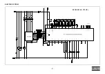
Страница 21: ... 21 ELECTRIC SYSTEM 9822 0963 40 C13 HP ...

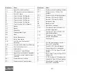
Страница 22: ...witch Airfilter PT1 Pressure sensor Vessel pressure Reference Name PT2 Pressure sensor Regulating Pressure PT3 Pressure sensor Oil stop valve pressure PT4 Pressure sensor Interstage pressure R2 Resistor 120 Ohm CAN J1939 R3 Resistor 120 Ohm CAN J1939 S1 Emergency Stop S4 Battery switch X9 Option box connector TT1 Temperature sensor PT1000 LP Element temperature TT2 Temperature sensor PT1000 HP ele...

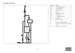
Страница 23: ...l pump preheater K6 Relay Preheater N4 Hydronic heater N5 Timer R1 Resistor 470 Ohm TS1 Thermostat F7 Circuit breaker 10A F15 Fuse 10A K5 Etherstart relay 1 Connect to 24M in cubicle 2 Connect to 24 VDC in power supply box 3 Connect to 19 in cubicle ...

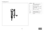
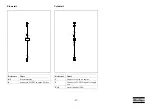
Страница 24: ... 24 Aftercooler sensors Reference Name 1 Connect to temperature input in cubicle default T IN 06 2 Connect to 18 in cubicle TT4 Temperature sensor PT1000 Aftercooler temperature ...

Страница 25: ...t in cubicle default T IN 01 2 Connect to 18 in cubicle 3 Connect to voltage input in cubicle default V IN 04 4 connect to 24VDC in power supply box 5 Connect to 29 in cubicle TT5 Temperature sensor PT1000 Air discharge temperature PT5 Pressure sensor Air discharge pressure ...

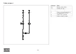
Страница 26: ... 26 Refinary equipment Reference Name K4 Relay kit 1604 3672 01 Y3 Air Shut off Valve 1 Connect to digital high output in cubicle default H OUT 10 2 Connect to 19 in cubicle 3 Connect to 24M in cubicle ...

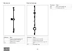
Страница 27: ...7 Etherstart Coldstart Reference Name K5 Etherstart relay 8 connect to D IN07 in spare I O box Reference Name 1 Connect to relay on engine 2 Connect to 24 VDC in power supply box F14 circuit breaker 100A ...

Страница 28: ...al high output in cubicle default H OUT 07 2 Connect to 19 in cubicle Y2 Bleeder Valve Reference Name 1 Connect to 19 in cubicle 2 Connect to 24 in cubicle 3 Connect to H OUT 06 in spare I O box P1 Refueling Pump Reference Name K3 Relay Refueling Pump F6 Circuit breaker 10A ...

Страница 29: ...nlet Outlet Compressor oil drain Read the instruction manual before starting Service every 24 hours Warning Part under pressure Do not stand on outlet valves Start Stop indication of switch Do not run the compressor with open doors Lifting permitted Use diesel fuel only Fork lifting permitted Don t lift here Read the instruction manual before lifting Filler cap coolant Read the instruction manual ...

Страница 30: ...aminated wind streams and walls Do not obstruct air evacuation from the cooling system Avoid recirculation of exhaust air from the engine This can cause overheating and engine power decrease The operator is expected to apply all relevant Safety precautions Before putting the compressor in to use check the brake system as described in section Brake shoe adjustment After the first 100 km travel Chec...

Страница 31: ...ck on the brakes by pulling button 3 TOWBAR LEVELLING WAGON The towbar of the wagon is equipped with an adjustable spring loaded levelling device To adjust 1 Slide back the rubber bellows 1 2 Turn the nut 2 clockwise to increase the spring load for lifting the towbar turn the nut 2 counter clockwise to decrease the spring load for lowering the towbar 3 Slide the bellows 1 over the nut Before towin...

Страница 32: ...will switch between three levels LARGE SMALL and OFF control interval The temperature thresholds have been fixed programmed in the electronic control device If the heat requirement at level SMALL is so low that the cooling water temperature reaches 85 C 185 F the device goes into control interval This is followed by the fan continuing to run for about 130 sec The signal lamp will stay lit during t...

Страница 33: ...deactivated after the set heating period has ended It has to be activated again for each new heating action Settings Commisioning After connecting the power all symbols in the display will blink Now the actual time has to be set before the heater can be operated Press button 1 time blinks Set time with buttons 2 or 3 Press button 1 time is displayed colon blinks Setting the time Press button 1 lon...

Страница 34: ... 3 With the compressor standing level check the level of the engine oil Add oil if necessary to the upper mark on dipstick Also check the engine coolant level Consult the Engine Operation Manual for the type of coolant and type and viscosity grade of the engine oil 4 Remove the air receiver drain plug 1 see figure and open the valve to drain possible condensate Close the valve when oil comes out a...

Страница 35: ...ne s to the closed air outlet valve s 13 Use hoses with suitable pressure rating and fit for the environmental conditions Always install the pull relief 2 see figure Inspect hoses and connections daily 14 Select fuel supply mode Internal supply Move the lever of the fuel selection supply valve upwards External supply Connect the supply and return hose to the fuel nipples at the fuel funnel Move th...

Страница 36: ...ontrol unit and wait until the display is dark before switching the battery switch to position OFF CONTROL PANEL Do not disconnect power supply to control box in any way when the control box is switched on This will cause memory loss Do not switch off the circuit breaker when the control box is switched on This will cause memory loss Please be aware that the optional preheater unit is still live w...

Страница 37: ...sing this button you can toggle between Measurements View and Main View SETTINGS VIEW button By pressing this button you can toggle between Settings View and Main View ALARMS VIEW button By pressing this button you can toggle between Alarms View and Main View NAVIGATION buttons These buttons are used to navigate through the display menu s ENTER button Confirms stores the selection change BACK butt...

Страница 38: ...info Main View Indication Measuring View Indication Settings View Indication Alarm View Indication DPF REGENERATION High Exhaust System Temperature Means that the Diesel Particle Filter is being regenerated DPF REGENERATION Diesel Particle Filter Regeneration Forced Means that Diesel Particle Filter will be regenerated as soon as all criteria to do so are met ...

Страница 39: ... dedicated icon PRESET Depending of which Pressure and or Flow setting is active the controller will show its dedicated icon Reference Name OPERATION MODE Local OPERATION MODE Remote OPERATION MODE PC Control OPERATION MODE Automatic OPERATION MODE Automatic Mode is active but the Auto Start and Auto Stop function are both inactive OPERATION MODE Block Mode ALARM Active not acknowledged Shutdown A...

Страница 40: ...lected and entered to access the sublist MAIN VIEW LOADED 1300RPM 22 4bar 41 1286h 22 4 MEASUREMENTS LOADED 1300RPM 22 4bar 41 1286h Running Hours 1286h ECU Engine rpm 1300 rpm ECU Requested Speed 1300 rpm ECU DPF Soot Load 24 Vessel Pressure 22 4 bar HP Element Temperature 101 C Ambient Temperature 27 C SETTINGS LOADED 1300RPM 22 4bar 41 1286h 1000 GENERAL SETTINGS 2000 DIGITAL INPUTS 3000 VOLTAG...

Страница 41: ...y opening the blow down valve After power up the vessel pressure normally is low enough to proceed with the starting procedure The display now shows The machine is now ready to be started and is waiting for a start command Xc3003 v1 00 0 r7307 If the Power switch is turned to the OFF position while the vessel is blowing down it will not power down for as long as the vessel pressure is higher than ...

Страница 42: ...l preheat according to the parameters of the engine controller Active Buttons Stop Button to cancel Start command Load Button to activate Automatic Load Measurement View Button Settings View Button Alarms View Button MAIN VIEW PREPARING FOR START 0 0 RPM 0 0bar 41 1286h MAIN VIEW READING ENGINE DATA 0 0 RPM 0 0bar 41 1286h Active Buttons Stop Button to cancel Start command Load Button to activate ...

Страница 43: ...ay shows The engine will run at minimum rpm until the engine s coolant temperature reaches 40 C with a minimum time of 15 seconds and a maximum time of 300 seconds 800RPM 324RPM 0RPM MAIN VIEW ENGINE CRANKING 324RPM 0 0bar 41 1286h Active Buttons Stop Button to cancel Start command Load Button to activate Automatic Load Measurement View Button Settings View Button Alarms View Button 120s 54s 0s MA...

Страница 44: ...mand Load Button to activate Automatic Load Measurement View Button Settings View Button Alarms View Button MAIN VIEW ENGINE WARMING UP 1200RPM 2 9 bar 41 1286h 15s 7s 0s Active Buttons Stop Button to cancel Start command Load Button to initiate Automatic Load Measurement View Button Settings View Button Alarms View Button MAIN VIEW READY TO LOAD 4 6 1200RPM 4 6bar 41 1286h ...

Страница 45: ...f the engine in order to meet the requested working pressure at the most economical fuel usage Active Buttons Stop Button to cancel Start command Load Button to cancel Load command Measurement View Button Settings View Button Alarms View Button MAIN VIEW BUILDING UP VESSEL PRESSURE 3 9 1200RPM 3 9bar 41 1286h Active Buttons Stop Button to cancel Start command Load Button to cancel Load command Mea...

Страница 46: ...rticulate filter is above 30 when a stop command is given the controller will ask the user if it is allowed to perform a complete DPF Regeneration cycle before stopping When ENTER is pressed the HEST icon will appear See paragraph DIESEL PARTICULATE FILTER REGENERATION The doors must be closed during operation and may be opened for short periods for inspection and adjustments only Be aware not to ...

Страница 47: ...in the OFF position It is not allowed to use this switch as an emergency switch or for stopping the compressor It can damage the controller or the engine s Electronic Control Unit when using the battery switch for stopping Always first shut off the controller and wait until the display is dark before switching the battery switch to position OFF Active Buttons Start Button to initiate Start command...

Страница 48: ... Soot Load LSR Low Speed Regeneration This can happen in following situations Warming Up Not Loaded Loaded when running in Unload condition minimum RPM Cooldown When an LSR is ongoing while the soot load is less than 60 and the engine speed changes engine is stopped machine gets loaded then the DPF Regeneration process will be stopped If the Soot Load is higher than 30 when cooling down should sta...

Страница 49: ...w the DPF Regeneration Needed Icon In case of Inhibited DPF Regeneration the DPF Regeneration Needed Icon will overwrite the DPF Inhibited Icon Required Action Force DPF Regeneration see paragraph FORCE DPF REGENERATION When DPF Regeneration is started the DPF Regeneration Needed icon will disappear and the HEST icon will pop up SOOT LOAD reaches 85 When no DPF regeneration is forced a warning ala...

Страница 50: ...the LOAD PREVENTION HIGH DPF SOOT LOAD inhibit load alarm press Enter while in the Main View Force DPF Regeneration see paragraph FORCE DPF REGENERATION When a DPF Regeneration is started the DPF Regeneration Needed icon will disappear and the HEST icon will pop up SOOT LOAD reaches 95 If still no action is taken the following warning appears and the controller will perform a controlled shutdown A...

Страница 51: ...enu Scroll one line down and Enter the 1140 ECU DPF REGENERATION menu OR Scroll down and Enter the MODE parameter Scroll down and Enter the AUTOMATIC setting Press the Back button 3 times to get back to the Main View DPF Regeneration setting will now be AUTOMATIC DPF REGENERATION Customer Level can now select between AUTO Regeneration INHIBIT Regeneration as long as the controller is not powered d...

Страница 52: ... to the preferred month and press ENTER To change any other RTC setting the red figure is editable Scroll up down and press ENTER to change Use left right to shift between editable figures Now press BACK until you re back in the Main View or in the menu you require Set Language Press the SETTINGS VIEW button scroll to 1000 GENERAL SETTINGS press ENTER scroll to 1300 LANGUAGES ENTER the LANGUAGES m...

Страница 53: ...ngine diagnostics Now press BACK until you re back in the Main View or in the menu you require To leave Diagnostics press the STOP button Set the Pressure Flow Setpoint only on AirXpert machines When the controller is in the Main View shift between PRESSURE and FLOW VIEW with right left arrows Press ENTER for 2 seconds and the middle section becomes green setting can be edited Press the UP DOWN ar...

Страница 54: ... Warning Xc 2000 EMERGENCY STOP INPUT Shutdown Xc 2040 REMOTE EMERGENCY STOP Shutdown Xc 2070 COOLANT LEVEL LOW WARNING Warning Xc 2080 COOLANT LEVEL LOW SHUTDOWN Shutdown Xc 2090 P AIRFILTERS HIGH Warning Xc 2100 NO PROJECTFILE DOWNLOADED Warning Xc 2752 NAM OILTRONIX BYPASS CIRCUIT Shutdown After Stop Xc 2762 NAM OILTRONIX CLOSED CIRCUIT Shutdown After Stop Xc 2772 NAM AIRXPERT OPENED CIRCUIT Sh...

Страница 55: ...IRCUIT Warning Xc 4150 H P ELEMENT TEMPERATURE ALARM 1 Warning Xc 4160 H P ELEMENT TEMPERATURE ALARM 2 Controlled Stop Xc 4170 H P ELEMENT TEMPERATURE ALARM 3 Shutdown Xc 4190 H P ELEMENT TEMP SENSOR CIRCUIT Shutdown Xc 4220 AFTERCOOLER AIR TEMP SENSOR CIRCUIT Warning Xc 4230 AFTERCOOLER FREEZING DANGER Indication Xc 5200 AIR SHUT OFF Shutdown Xc 6190 CHARGE MONITORING FAIL Indication Xc 6327 STAR...

Страница 56: ...ESSURE ECU COOLANT TEMPERATURE ECU COOLANT LEVEL ECU SUPPLY VOLTAGE ECU AMBIENT AIR TEMPERATURE ECU AIR INLET TEMPERATURE ECU FUEL TEMPERATURE ECU OIL TEMPERATURE ECU ENGINE SPEED ECU INJECTOR 1 ECU INJECTOR 2 ECU INJECTOR 3 ECU INJECTOR 4 ECU INJECTOR 5 ECU INJECTOR 6 ECU INJECTOR 7 ECU INJECTOR 8 ECU SOOT LOAD 6981 INLET VALVE POS FAILURE Shutdown Xc 7002 ECU COMMUNICATION Shutdown Xc 7007 ECU R...

Страница 57: ...rminated by the emergency stop itself hardware as well as by the software When the emergency stop button 1 is pressed the operator can unlock the emergency stop by turning it counterclockwise The emergency stop button is only to be used in emergency situations not for stopping procedures 1 ...

Страница 58: ...now perform a brief selftest Push the start button and the starter motor will automatically try to start the engine 1 2 After cleaning draining the fuel tanks the system is filled with air Before starting the engine operate the fuelpump on the fuelfilter to fill the fuelsystem Loosen the vent screw 1 on the fuel filter Operate the hand pump 2 at the filter until fuel comes out of the bore for the ...

Страница 59: ...r Service Paks at your local Atlas Copco dealer SERVICE KITS A service kit is a collection of parts to fit a specific repair or rebuilding task It guarantees that all necessary parts are replaced at the same time which improves the uptime of the unit The order numbers of the Service Kits are listed in the Atlas Copco Parts List ASL STORAGE Run the compressor regularly e g twice a week until warm L...

Страница 60: ... maintenance can void any warranty claims MAINTENANCE SCHEDULE COMPRESSOR To determine the maintenance intervals use service hours or calendar time whichever occurs first Service hours Daily 50 hrs after initial start up Every 250 hrs Every 500 hrs Every 750 hrs Every 1000 hrs Every 2000 hrs Yearly Service parts 1092061334 PAK 3002 6071 00 PAK For the most important subassemblies Atlas Copco has d...

Страница 61: ...heck function of coolant heater option x Check control panel x Check on abnormal noise x Check electrical system cables for wear x Check for leaks in engine compressor air oil or fuel system x x x x x Check torque on critical bolt connections x x x x Check electrolyte level and terminals of battery x x x x x Check engine minimum and maximum speed x x x x x Replace compressor oil filter s 5 x x x x...

Страница 62: ... protective devices x Clean oil cooler s 1 x x x x Clean radiator 1 x x x x Clean intercooler 1 x x x x Analyse coolant 4 8 x Inspect starter motor x x x Inspect turbocharger x x x Inspect waterpump x x x Check engine protective devices x Test safety valve 9 x x x Replace bleed off valve unloader x x x Check rubber flexibles 11 x x x Check emergency stop x Clean after cooler option 1 x x x Replace...

Страница 63: ... is only valid when using PARCOOL Change coolant every 5 years 5 Use Atlas Copco oil filters with by pass valve as specified in the parts list 6 Gummed or clogged filters means fuel starvation and reduced engine performance 7 See section Oil specifications 8 The following part numbers can be ordered from Atlas Copco to check on inhibitors and freezing points 2913 0028 00 refractometer 2913 0029 00...

Страница 64: ...overrun brake x x x Check brake system if installed and adjust if necessary x x x Oil or grease brake lever and moving parts such as bolts and joints x x x Check Adjust lateral play of wheel bearing x x x Check tyres for uneven wear x x Grease sliding points on height adjusting parts x x Check safety cable for damage x x Check Bowden cable on height adjustable connection device for damage x x Lubr...

Страница 65: ...irculation of the synthetic oil Then drain the synthetic oil again and fill again with new synthetic oil To set correct oil levels proceed as in normal instruction COMPRESSOR OIL Synthetic compressor oil PAROIL S Synthetic compressor oil PAROIL S xtreme Liter US gal Order number can 5 1 3 1630 0160 00 can 20 5 3 1630 0161 00 barrel 210 55 2 1630 0162 00 container 1000 264 1630 0163 00 Liter US gal...

Страница 66: ...ead of allowing them to clog your filter and accumulate in the valve rocker cover area PAROIL releases excess heat efficiently whilst maintaining excellent bore polish protection to limit oil consumption PAROIL has an excellent Total Base Number TBN retention and more alkalinity to control acid formation PAROIL prevents Soot build up PAROIL is optimized for the latest low emission EURO 3 2 EPA TIE...

Страница 67: ...evel according to the instructions in the Engine Operation Manual and if necessary top up with oil CHECK COMPRESSOR OIL LEVEL With the compressor standing horizontal check the level of the compressor oil The pointer of the oil level gauge 1 must register in the upper extremity of the green range Add oil if necessary Before removing the oil filler plug 2 ensure that the pressure is released by open...

Страница 68: ...s until the pressure is released through the automatic blow down valve Make sure that all pressure is released by loosening the filler plug 1 one turn 2 Wait a few minutes until the oil level is constant 3 Remove the filler plug 1 and top up with oil until the pointer of the oil level gauge 2 is in the upper part of the green area 4 Reinstall and tighten the filler plug 1 1 2 ...

Страница 69: ... drain plugs 4 Catch the oil in a drain pan Screw out the filler plug 2 to speed up draining After draining place and tighten the drain plugs 4 3 Remove the oil filters 1 e g by means of a special tool Catch the oil in a drain pan 4 Clean the filter seat on the manifold taking care that no dirt drops into the system Oil the gasket of the new filter element Screw it into place until the gasket cont...

Страница 70: ...sor oil filter s and close the oil vessel according to the instructions 6 Fill the oil vessel with the minimum amount of replacement oil run the compressor under light load conditions for 30 minutes 7 Thoroughly drain the system when the oil is warm leaving as little oil in the system as feasible especially in dead areas if possible blow out remaining oil by pressurising the oil 8 Fill the system ...

Страница 71: ...COOL EG inhibits corrosion deposit formation is minimized This effectively eliminates the problem of restricted flow through the engine coolant ducts and the radiator minimizing the risk for engine overheating and possible failure It reduces water pump seal wear and has excellent stability when subjected to sustained high operating temperatures PARCOOL EG is free of nitride and amines to protect y...

Страница 72: ...RCOOL EG COOLANT CHECK In order to guarantee the lifetime and quality of the product thus to optimise engine protection regular coolant condition analysis is advisable The quality of the product can be determined by three parameters Visual check Verify the outlook of the coolant regarding colour and make sure that no loose particles are floating around pH measurement Check the pH value of the cool...

Страница 73: ... 5 5 6 0 5 6 7 8 9 10 11 12 13 14 15 16 1 2 3 4 5 Example Total volume coolant Measured concentration In case of expansion tank at low level this quantity is to be filled without draining from the cooling system 1 Refractometer indication 20 C 33 2 Refractometer indication 22 C 3 Refractometer indication 25 C 4 Refractometer indication 30 C 5 Refractometer indication 36 C Liter Vol Liter PARCOOL E...

Страница 74: ...otal volume coolant Measured concentration In case of expansion tank at normal level this quantity is to be drained from the cooling system 1 Refractometer indication 20 C 33 2 Refractometer indication 22 C 3 Refractometer indication 25 C 4 Refractometer indication 30 C 5 Refractometer indication 36 C Liter Vol Liter PARCOOL EG Concentrate PN 1604 8159 00 4 8 12 16 20 24 28 32 36 40 44 48 52 56 60...

Страница 75: ...e until normal engine operation temperature is reached Turn off the engine and allow to cool Recheck coolant level and add if necessary CLEANING COOLERS Keep the coolers 1 2 and 3 clean to maintain the cooling efficiency Service doors 4 are provided on both sides of the fan cowl to allow easy access to the fan side surface of the coolers Clean by air jet in the direction of the arrow Steam cleanin...

Страница 76: ...and after charging a battery always check the electrolyte level in each cell if required top up with distilled water only When charging batteries each cell must be open i e plugs and or cover removed Apply with preference the slow charging method and adjust the charge current according to the following rule of thumb Battery capacity in Ah divided by 20 gives safe charging current in Amp BATTERY MA...

Страница 77: ...e pressure and decreased to lower it by turning the adjusting wheel clockwise and anti clockwise respectively To adjust the normal working pressure proceed as follows 1 Loosen the lock nut of the regulating valve 2 Release Regulating Valve turn out 3 With the outlet valves 2 closed adjust the regulating valve 1 until a pressure is reached of nominal pressure 2 bar 29 psi 4 Lock the regulating valv...

Страница 78: ...dge 3 is an indication of a malfunctioning filter element 3 Reassemble in reverse order of dismantling 4 Inspect and tighten all air intake connections 1 Snap clips 4x 4 Filter element 2 Dust trap cover 5 Filter housing 3 Safety cartridge 6 Vacuator valve The Atlas Copco air filters are specially designed for the application The use of non genuine air filters may lead to severe damage of the engin...

Страница 79: ...rder to purge trapped air see paragraph Specific start procedure The fuel system should be primed under the following conditions Compressor is put in operation for the first time Running out of fuel Storage Replacement of the fuel filter Daily drain condensate 2 1 All adjustments or repairs are to be done by an authorized representative of the safety valve 2 supplier see section Specific safety pr...

Страница 80: ...mp 5 Close vent when fuel begins to purge 8 Check for leaks retighten if necessary Drain instructions 1 Open bowl drain valve 1 operate pump 5 and pump water out 2 Close drain valve 1 CLEANING CRANKCASE BREATHER FILTER 1 After switching off the engine let it cool down for about 30 minutes 2 Open the clasps 2 and carefully separate the bowl from the head Be aware that hose 3 is still attached 3 Tak...

Страница 81: ...pling parts Leaks at the fitting valve or mating seal Broken coupling mounting hardware especially breakaway clamps Visual inspection all other Leaking seals or port connections Excess dirt build up on the coupling locking means or on the interface area of either coupling half Defective clamps guards and shields Fuel level system and any entrapment Functional test Operate the system at maximum ope...

Страница 82: ...1 by approximately one turn until no braking effect can be felt when the wheel is turned in a forward direction Check the position of the brake equalizer compensators with the parking brake applied Positioned at right angles to the brake rods even play on both wheel brakes Re adjust brakes if necessary As a check apply the parking brake slightly and check that the braking effect on the wheels in t...

Страница 83: ...ng brake lever several times by hand with a force of 200 to 300 N and put it back into the not engaged tooth 1 position Adjust the turnbuckle 8 as described above Testing the parking brake For testing the parking brake apply the parking brake lever Brake power must be reached between the 6th and 14th tooth of the toothed segment Z 10 Z 9 7 Y Y 11 11 8 Z 14 6 1 Tighten all lock nuts 11 Torque 24 Nm...

Страница 84: ... an Atlas Copco Service representative Blow down valve stuck in open position Check and correct as necessary Loading valve LV leaking past O ring With compressor running at max load speed disconnect hose leading to unloader If air leaks from the hose remove and inspect loading valve Replace damaged or worn O rings Oil separator element clogged Have element removed and inspected by an Atlas Copco S...

Страница 85: ...ews first remove the short screws then release the spring tension unscrewing the long ones Minimum pressure valve malfunctioning Remove and inspect valve Blow off valve malfunctioning Remove and inspect valve Possible faults Corrective actions Engine oil pressure too low Refer to the engine instruction manual Compressor or engine overheating See corrective actions Compressor overheating Fuel tank ...

Страница 86: ...nt compressor cooling Locate compressor away from walls when banked with other compressors leave space between them Oil cooler clogged externally Clean oil cooler Refer to section Cleaning coolers Oil cooler clogged internally Consult Atlas Copco Oil filters clogged Replace oil filters Oil level too low Check oil level Top up with recommended oil if necessary Thermostatic by pass valve remains stu...

Страница 87: ...em Heater shuts off Problem Control unit locked Possible faults Corrective actions No fuel Check fuel level Fuse blown Check fuse Bad electrical contact Check electrical wiring Blocked air duct or exhaust gas duct Check combustion air duct and exhaust gas duct Glow plug defective Replace glow plug Fan motor defective Replace fan motor Possible faults Corrective actions Overheating Cool down and st...

Страница 88: ...is needed This option exits of rubber damped axles four wheels and a tow bar The wheels are also equipped with brakes operated from the brake handle on the tow bar SUPPORT MOUNTED With the option Support mounted it is possible to fix the compressor to a truck for more flexibility or to a frame when it is to be used permanently in an installation ...

Страница 89: ...fuel filter gives an extra protection to the fuel combustion system SPARK ARRESTOR The certified spark arrestor is an addition to the exhaust that makes it possible to operate the compressor in hazardous environments like refineries where there is a possibility that inflammable fumes can be released The spark arrestor prevents any hot burning particles from getting into the open air ...

Страница 90: ...n COLD WEATHER PACKAGE The cold start option consists of larger batteries and a blow off valve to be able to start the engine at temperatures between 10 C 14 F and 25 C 13 F It also includes a preheater INLET SHUTDOWN VALVE The inlet shut down valve is a safety device preventing the engine from over speeding when sucking in combustible fumes When the engine max RPM is exceeded a pneumatically cont...

Страница 91: ... at temperatures kept as low as possible The OILTRONIX is standard on the XRXS and XRYS types and option on the XRVS types FUELXPERT This is a control module that regulates engine speed and the air inlet to optimise fuel consumption depending on the working conditions and the output required PRESSURE REGULATOR EC A pressure regulating system according to European standards for reducing the operati...

Страница 92: ... compressor controller A warning can be set at a value between 0 C and 115 C default value and a shut down can be set at a value between 0 C and 120 C default value The operator has authority to modify these values so the process can be guarded and kept in a safe condition under all circumstances See also table Fault codes on page 54 The installation includes a by pass over the after cooler For ap...

Страница 93: ...100 M14 210 155 M16 345 255 Assemblies Torque value Nm lbf ft Axles to frame Wheel nuts 270 200 Bolts front axle frame 205 152 Bolts rear axle frame 205 152 Compressor to frame Bolts elements gear casing 46 34 Bolts elements support 80 60 Bolts support buffer 205 152 Bolts buffer frame 80 60 Engine to frame Bolts engine support 205 152 Bolts support buffer 46 34 Bolts buffer frame 23 17 Lifting be...

Страница 94: ...e C 20 20 F 68 68 Nominal effective working pressure bar e 20 25 psi 290 363 Designation XRHS 527 Cd XRHS 1150 CD6 XRVS 487 Cd XRVS 1050 CD6 Minimum effective receiver pressure bar e 12 5 15 5 psi 181 225 Maximum effective receiver pressure compressor unloaded bar e 22 27 psi 319 392 Maximum ambient temperature at sea level C 45 45 F 113 113 Minimum starting temperature C 10 10 F 14 14 Minimum sta...

Страница 95: ...pert kg h 64 4 64 4 lb h 141 98 141 98 No Fuel expert kg h 66 8 64 88 lb h 145 68 143 04 at 75 FAD Fuel expert kg h 47 4 47 4 lb h 104 5 104 5 No Fuel expert kg h 54 12 55 68 lb h 119 31 122 75 at 50 FAD Fuel expert kg h 38 88 38 88 lb h 85 72 85 72 No Fuel expert kg h 45 28 46 56 lb h 99 83 102 65 at 25 FAD Fuel expert kg h 34 4 34 4 lb h 75 84 75 84 No Fuel expert kg h 33 24 36 68 lb h 73 28 80 ...

Страница 96: ...lies with ISO 2151 EPA under free field conditions at 7 m distance dB A 83 4 83 39 Sound power level LW complies with 2000 14 EC dB A 108 62 108 27 Sound power level LW complies with 84 533 EEC and 85 406 EEC limits dB A Tolerance 5 25 l s 53 cfm FAD 250 l s 530 cfm 4 250 l s 530 cfm FAD The international standard ISO 1217 corresponds to following national standards British BSI 1571 part 1 German ...

Страница 97: ... 97 ALTITUDE UNIT PERFORMANCE CURVE Max allowable working pressure as a function altitude and ambient temperature ALTITUDE m ALTITUDE ft TEMPERATURE F TEMPERATURE C ...

Страница 98: ...erpillar Type C13 ATAAC Coolant Liquid Number of cylinders 6 Bore mm 130 in 5 12 Stroke mm 157 in 6 18 Swept volume l 12 5 cu in 762 75 Output acc to DIN 6271 at normal shaft speed kW 328 hp 440 Load factor 1 70 Designation All units Capacity of oil sump Initial fill l 36 US gal 9 51 Refill max 2 l 34 US gal 8 98 Capacity of cooling system l 60 US gal 15 85 ...

Страница 99: ...ity of air receiver l 143 US gal 37 78 Capacity of fuel tanks wagon tandem l 796 US gal 210 Air volume at inlet grating approx 1 m3 s 14 6 Cu ft s 516 Designation All units Length m 4 05 inch 159 45 Width m 2 15 inch 84 64 Height m 2 25 inch 88 58 Towbar Wagon Support weight ready to operate mounted skid XRHS527 XRHS1150 Kg 5745 5105 5605 lbs 12665 11254 12537 XRVS487 XRVS1050 Kg 5745 5105 5605 lb...

Страница 100: ... 100 Dataplate 1 Name of the manufacturer 2 Vehicle identification number 3 Model 4 Serial Number 5 Working pressure 6 Speed 7 Engine power 8 Manufacturing year ...

Страница 101: ...RHS 527 Cd XRHS 1150 CD6 XRVS 487 Cd XRVS 1050 CD6 Set pressure bar e 20 25 psi 290 363 Design temperature C 130 130 F 266 266 Designation Standard Cold start equipment Design pressure bar e 30 30 psi 435 435 Design temperature max C 130 130 F 266 266 Design temperature min C 10 25 F 14 13 Volume l 143 143 US gal 38 38 Imp gal 31 31 cu ft 5 5 ...

Страница 102: ... 102 PARTS SUBJECTED TO CAT I AND COVERED BY THE MACHINE DIRECTIVE 89 392 EC All other parts PARTS SUBJECTED TO ART I PARAGRAPH 3 3 All other parts ...

Страница 103: ...materials for recycling in the future is forseen DISPOSAL OF MATERIALS Dispose contaminated substances and material separately according to local applicable environmental legislations Before dismantling a machine at the end of its operating lifetime drain all fluids and dispose of according the applicable local disposal regulations Remove the batteries Do not throw batteries into the fire explosio...

Страница 104: ... 104 Maintenance Log Compressor Customer Serial number Service hours Maintenance action Date By initials ...

Страница 105: ......

Страница 106: ...www atlascopco com ...

Отзывы: