background image

15

PAGE

Repair Instructions Nr.183.09/00

PHE 50 S

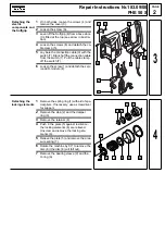
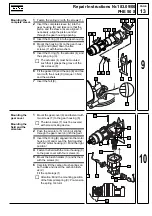
Mounting the 
electric 
components and 
the Softgrip

1

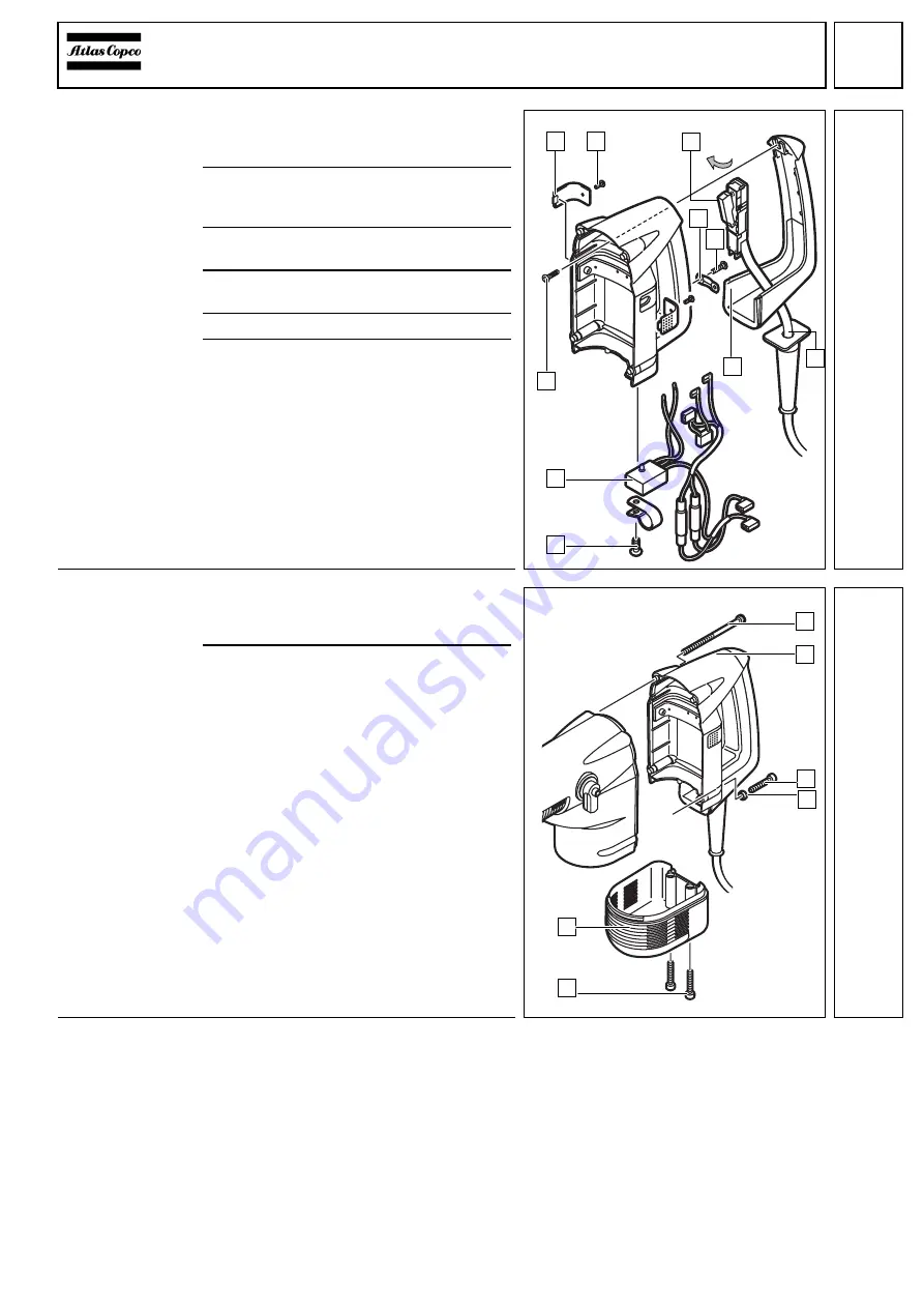
Insert the service LED-module with RTR 
chip (2) into the housing and fix it with the 
screw (1).

2

Lead the connection cable (9) through the 
Softgrip (8) and connect the switch (7) 
with the RTR chip (2).

3

Fix the connection cable (9) with aid of the 
cable clamp (5) and the screw (6).

4

Hang up the Softgrip (8) at the top of the 
handle and press it down.

5

Mount the screw (A) to fix the Softgrip (9).

6

Fit the cover (3) on both sides and fix it 
with the screws (4).

Fastening the 
complete handle 
and the motor 
cover

1

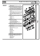
Push the complete handle (4) over the 
housing and fasten it with the screws (3) 
and (5) as well as the distance sleeve (6).

2

Fix the motor cover (2) with two
screws (1).

Test Run

Electrical Test

Test run the machine and pay attention to noises.

Let the machine run-in.

Perform an electrical test on the machine (see chapter Electrical and Mechanical Test Instructions).

1

4

3

2

6

8

5

9

A

7

13

1

2

4

5

3

6

14

Содержание PHE 50 S

Страница 1: ......

Страница 2: ...strument to check for a possible maintenance interval Disassembly Detaching the trigger 1 Loosen the screw 8 and remove the trig ger 7 with cover 2 Loosen both screws 1 and remove the motor cover 2 3...

Страница 3: ...ull the cable clamp off the switch 7 6 Loosen the screw 1 and detach the serv ice LED module 2 Detaching the locking elements 1 Remove the spring ring 1 with aid of spe cial pliers If necessary use a...

Страница 4: ...rubber sleeve of the armature bearing Pull out the armature 5 manually if necessary use a plastic hammer for support light blows 6 Undo the two screws 7 in the gear cover 6 and pull off the gear cover...

Страница 5: ...ring 5 from the drill spin dle 3 4 Remove the following parts from the spin dle sleeve F ring 9 rubber ring A ring B 5 Remove the O ring C and the locking ring D from the spindle sleeve F and press o...

Страница 6: ...Detach the seal ring 3 Detaching the field 1 Remove the air deflector ring 4 from the motor housing 1 2 Loosen both screws 3 with their washers and expel the field 2 from the motor housing 1 Detaching...

Страница 7: ...2 and pull out the connecting rod 5 3 Press the bearing 4 from the connecting rod 5 Dismantling the drive 1 Align the drive wheel 4 with the borings of the screws 7 Loosen both screws 7 and remove the...

Страница 8: ...cold cleaning agent Caution No cleaning agent should penetrate into the bearing Clean the electrical parts with a dry brush Check for wear Check the disassembled parts for wear visual inspection and r...

Страница 9: ...9170 304 322 C Cover with Tivela Compound A 10 g 493170 215 436 Torques Screws in plastic 1 5 Nm Screws in metal 4 0 Nm Motor housing screws 1 4 0 Nm Flange screws gear 2 10 0 Nm Screw locking device...

Страница 10: ...e discs 3 and 5 with blue grease type Mobilith HP 222 2 Mount the spring ring 1 depressing the spring plate 2 at the same time 3 Insert the assembled drive into the gear housing C and fix it with scre...

Страница 11: ...rom below and hang it in the connecting rod 3 Insert the locking ring 1 with aid of spe cially cut pliers between toothed wheel and gear housing 3 The locking ring 1 must cover the bor ing 4 dotted li...

Страница 12: ...ht position and se cure it with screws 3 and washers tightening moment 8 Nm 2 Fit the air deflector ring 4 on the motor housing 1 Mounting the armature 1 Mount the seal ring 3 on the armature shaft Pr...

Страница 13: ...e striker U into the spindle sleeve F The O ring V must face the direction of the four lips seal ring of the piston 6 Insert the ring B the rubber ring A and the ring 9 into the spindle sleeve F 7 Fit...

Страница 14: ...3 Nm and the washers 7 Insert the felt 8 Mounting the gear cover Mounting the field and the armature 1 Mount the gear cover 6 and fasten it with two screws 7 to the gear housing 8 The two screws 7 mu...

Страница 15: ...le Place the machine on its side on a mat 1 to prevent the plate springs from falling down 1 Place 2 plate springs 1 and 2 on the trigger First fit the spring with the side shap ing 2 then fit the spr...

Страница 16: ...8 at the top of the handle and press it down 5 Mount the screw A to fix the Softgrip 9 6 Fit the cover 3 on both sides and fix it with the screws 4 Fastening the complete handle and the motor cover 1...

Отзывы: