14
PAGE
Repair Instructions Nr.183.09/00
PHE 50 S
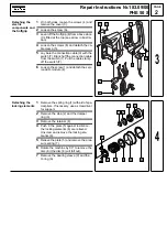
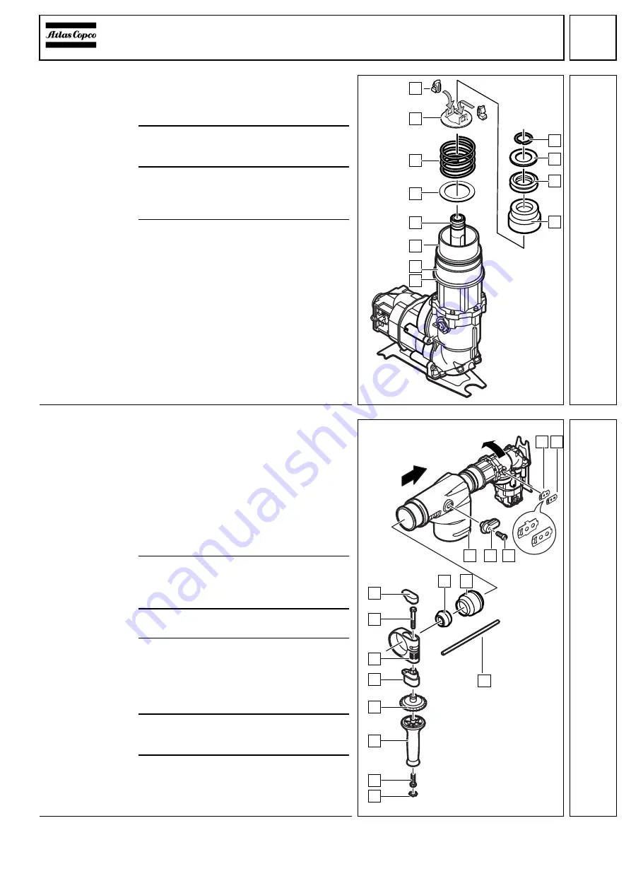
Mounting the
locking elements
1
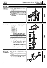
For further assembly, rotate the machine
as shown in illustration:
Push the O-ring (1) and the bearing
sleeve (2) over the housing (3).
2
Place the disc (5) and the pressure
spring (6) between housing (3) and spin-
dle sleeve (4).
3
Place the plate (7) on the pressure
spring (6) and depress the latter. Let the
locking elements (8) engage in the
plate (7) and the spindle sleeve (4).
4
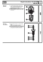
Fit the retainer (9), the damper ring (A) as
well as the stop (B) and secure them with
the spring ring (C).
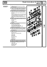
Mounting the
trigger,
Mounting the
handle
☞
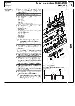
Place the machine on its side on a
mat (1.), to prevent the plate springs
from falling down!
1
Place 2 plate springs (1) and (2) on the
trigger.
☞
First fit the spring with the side shap-
ing (2) then fit the spring without the
side shaping (1). If necessary, break
off the side shapings of plate
spring (1).
2
Fit the gear housing insulation (5) to the
machine.
Mount the trigger (4) and secure it with the
screw (3). Mind the right position!
3
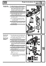
Fit the sleeve (6) and push back and press
on the end cover cap (7).
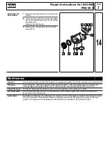
4
The following parts must be mounted:
clamping ring (A),
screw (9),
plastic cover (8),
support (B),
clamping ring (C).
5
Insert the fan type lock washer (F) into the
handle (D), fit the screw (E) and screw
down the handle (D).
6
Mount (G) the depth gauge.
1
2
5
4
3
6
7
A
9
8
B
C
11
1
4 3
2
6
5
7
G
8
9
A
B
C
D
E
F
1.
12
Содержание PHE 50 S
Страница 1: ......


