2920 1449 00
8
Instruction book
1.2.3 Oil system
Air pressure forces the oil from receiver (17) through oil coolers
(6), filters (7) and oil stop valve (15) to the compressor elements
and the lubrication points.
Oil stop valve (15) prevents the compressor element from
flooding with oil when the compressor is stopped.
Valve (26) by-passes oil coolers (6) when starting the
compressor from cold condition, to ensure rapid warming of
the oil to normal working temperature.
In air receiver (17) most of the oil is removed from the air
centrifugally. Almost all of the remaining oil is removed by
separator element (18).
1.2.4 Cooling system
On GR, the system includes air cooler (4) and oil coolers (6),
cooled by one or two fans (5) 1).
GR W are provided with a cooling water system, including a
combined oil and air cooler.
1.2.5 Regulating system
The system keeps the net pressure within programmable
pressure limits by automatically loading and unloading the
compressor depending on the air consumption. It is controlled
by Elektronikon
®
regulator (E1) which also protects the
compressor and monitors components subject to service. See
section 1.3.
Unloading
If the air consumption is less than the air delivery of the
compressor, the net pressure increases. When the net pressure
reaches the upper limit of the working pressure (unloading
pressure), solenoid valve (Y1) is de-energized. The plunger of
the valve moves downwards by spring force:
1. The plunger of solenoid valve (Y1) shuts off the supply of
receiver pressure towards chamber (8).
2. Control pressure present in chamber (8) is vented to
atmosphere through loading solenoid valve (Y1). Unloading
valve (3) closes by spring force.
3. Valve (12) is pushed downwards releasing receiver pressure
through flexible (30) and channels (10 and 29) towards the
air inlet. As long as the pressure in the air receiver is higher
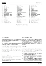
1
Air filter
2
Unloader
3
Unloading valve
4
Air cooler
5
Cooling fan
6
Oil coolers
7
Oil filters
8
Chamber, control pressure
9
By-pass opening
10
Primary blow-off channel
11
Chamber, receiver pressure
12
Valve
13
Shield
14
Compressor element, low pressure
15
Oil stop valve
16
Check valve
17
Air receiver
18
Oil separator element
19
Minimum pressure valve
20
Check valve
21
Oil scavenging line
22
Safety valve
23
Oil filler plug
24
Oil level indicator
25
Oil drain plug
26
By-pass valve
27
Air outlet valve (customer’s
installation)
28
Condensate trap
29
Channel
30
Flexible, receiver pressure
31
Insulating block
32
Condensate trap
33
Liquid – gas mixer
34
Thermostatic expansion valve
35
Sight-glass
36
Filter/dryer
37
Capillary tube
38
Fan control switch
39
High pressure switch
40
Fan
41
Fan motor
42
Condenser
43
Hot gas by-pass valve
44
Refrigerant compressor
45
Liquid separator
46
Low pressure switch
47
Air/refrigerant heat exchanger
48
Air/air heat exchanger
49
By-pass valves
50
By-pass valve
51
Vent valve
52
Secondary blow-off channel
53
Compressor element, high pressure
E1 Elektronikon regulator
M1 Drive motor
Y1 Loading solenoid valve
Figs. 1.4 and 1.5 Regulating system
Содержание GR110
Страница 6: ...2920 1449 00 6 Instruction book Fig 1 4 GR Full feature during unloading ...
Страница 7: ...2920 1449 00 7 Instruction book Fig 1 5 GR Full feature during loading ...
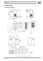
Страница 14: ...2920 1449 00 14 Instruction book Fig 2 2 Dimension drawing GR110 W up to GR200 W ...
Страница 15: ...2920 1449 00 15 Instruction book Fig 2 3 Installation proposal 2 2 Installation proposals Fig 2 3 ...


