background image

2920 1449 00

33

Instruction book

6 PROBLEM SOLVING

Warning

Before carrying out any maintenance, repair or
adjustment, stop the compressor, press emergency
stop button (S2-Fig. 3.5) and switch off the
voltage.  Close the air outlet valve and open the
manual condensate drain valve(s). 1)

Take precautions to avoid an accidental restart.
Apply all relevant safety precautions, including
those mentioned in this book.

Faults and suggested remedies

1

A service message appears on the display
Replace the indicated component or grease the drive motor
as the case may be.  Consult the "User manual for
Elektronikon regulator" to remedy the trouble and to reset
the message (section "Submenu SERVICE")

2

A shut-down warning message appears on the display
LED (3-Fig. 1.6) will light up indicating that the temperature
at the outlet of the compressor elements is too high.  See
below.  The message disappears as soon as the cause of the
trouble is remedied

3

Unit is shut-down
LED (3-Fig. 1.6) will blink indicating either that the outlet
temperature is too high (see below) or that the motor
overload relay has tripped.  Consult the "User manual for
Elektronikon regulator" to remedy the trouble and to reset
the message (section "Submenu STATUS DATA")

4

Condensate is not discharged from condensate trap(s)
during loading

a

Discharge pipe of condensate trap clogged

a

Check and correct as necessary

b

Float valve of condensate trap(s) malfunctioning

b

Remove float valve assembly, clean and check

5

Compressor air delivery or pressure below normal

a

Air consumption exceeds air delivery of compressor

a

Check equipment connected

b

Choked air filters

b

Replace filters

c

Air leakages

c

Check and correct

6

Compressor elements outlet temperature or delivery air
temperature above normal

a

Insufficient cooling air

a

Check for cooling air restriction.  Improve ventilation of
compressor room.  Avoid recirculation of cooling air

b

On GR W, cooling water temperature too high or flow too
low

b

See section 7.5.  Increase water flow and check temperature

c

Oil level too low

c

Check and correct as necessary

d

Oil coolers clogged

d

Consult Atlas Copco

e

Air cooler clogged

e

Consult Atlas Copco

f

On GR W, restriction in cooling water system due to dirt or
formation of scale

f

Consult Atlas Copco

7

If an oil/water separator (OSD) is provided: turbulences
in separator vessel

a

Air leakage through condensate flexible towards vessel

a

Remove float valve assembly, clean and check

Footnote chapter 6

1) On compressors with optional OSD separator, a valve is fitted

underneath the condensate trap.  Close the valve after repairing.

Содержание GR110

Страница 1: ... thereof is prohibited This applies in particular to trademarks model denominations part numbers and drawings This instruction book meets the requirements for instructions specified by the machinery directive 98 37 EC and is valid for CE as well as non CE labelled machines Important 1 This book applies to the compressors from serial number AIF 073 956 onwards 2 This book must be used together with...

Страница 2: ...erload relay and fuses for 60 Hz IEC compressors 35 7 4 3 Motor overload relay and fuses for 60 Hz CSA UL compressors 35 7 4 4 Fan motor circuit breakers 36 7 4 5 Circuit breakers for dryer motor GR Full feature 36 7 4 6 Circuit breakers for dryer cooling fan motor GR Full feature 37 7 4 7 Circuit breaker for control circuit 37 7 5 Compressor specifications 38 7 5 1 Reference conditions 38 7 5 2 L...

Страница 3: ...ces the required space for installation and provides savings on piping installation cost Integrated DD filter only on GR W 13 bar 200 psi Full feature compressors can be provided with an integrated filter of the DD type to limit carry over of solid particles and oil By integrating a DD filter the GR Full feature turns into a fully integrated compressed air station delivering Quality Air according ...

Страница 4: ...fety valve 3 Air cooler 4 Bolts 5 Oil coolers 6 Filler plug only to be used at initial start up 7 Unloader 8 Air inlet hose 9 Compressor element low pressure 10 Check valve 11 Compressor element high pressure 12 Oil drain plug air receiver 13 Air receiver 14 Oil filters 15 Oil separator element 16 Receiver cover 17 Bolt 18 Minimum pressure valve 19 Arrow rotation direction fan motor 20 Cooling fan...

Страница 5: ...ture of the windings The readings can be called up on the display of the Elektronikon regulator A message will appear on the display and the general alarm LED will light up if one of the temperatures exceeds the shut down warning setting BSP or NPT connections For GR110 up to 200 a BSP or NPT connection can be chosen Communication module COM1 COM2 module allows remote communication and monitoring ...

Страница 6: ...2920 1449 00 6 Instruction book Fig 1 4 GR Full feature during unloading ...

Страница 7: ...2920 1449 00 7 Instruction book Fig 1 5 GR Full feature during loading ...

Страница 8: ...rce 1 The plunger of solenoid valve Y1 shuts off the supply of receiver pressure towards chamber 8 2 Control pressure present in chamber 8 is vented to atmosphere through loading solenoid valve Y1 Unloading valve 3 closes by spring force 3 Valve 12 is pushed downwards releasing receiver pressure through flexible 30 and channels 10 and 29 towards the air inlet As long as the pressure in the air rec...

Страница 9: ...e motor in case of wrong phase connection if a phase sequence relay is provided as an option and also in case of fan motor overload Remedy the trouble and reset the message on the display before restarting See User manual for Elektronikon regulator section Submenu STATUS DATA Shut down warning Before the shut down level for the outlet temperature of the compressor or compressor elements is reached...

Страница 10: ...ve in automatic operation The LED goes out after unloading the compressor manually 9 Stop button Push button to stop the compressor LED 1 goes out The compressor will run unloaded for 30 seconds before stopping S2 Emergency stop Push button to stop the compressor button immediately in case of emergency After remedying the trouble unlock the button by pulling it out S5 Control mode Key switch to se...

Страница 11: ...s and number of motor starts Service Calling up and resetting the service messages for the oil oil filters oil separator air filters Test Allows a display test Modify settings Modifying the settings for regulation e g loading and unloading pressures for protection e g temperature shut down level and for service e g for the oil Program Description Function Timer Programming automatic compressor sta...

Страница 12: ...tage before connecting external equipment Footnotes chapter 1 1 GR110 are provided with one fan GR132 up to GR200 are provided with two fans 2 This function is called the Timer function See User manual for Elektronikon regulator section Submenu TIMERS F3 5 Circuit breakers F21 Compressor motor overload relay K11 Auxiliary relay loading K21 Line contactor K22 Star contactor K23 Delta contactor K25 ...

Страница 13: ...2920 1449 00 13 Instruction book 2 INSTALLATION 2 1 Dimension drawings Fig 2 1 Dimension drawing GR110 up to GR200 ...

Страница 14: ...2920 1449 00 14 Instruction book Fig 2 2 Dimension drawing GR110 W up to GR200 W ...

Страница 15: ...2920 1449 00 15 Instruction book Fig 2 3 Installation proposal 2 2 Installation proposals Fig 2 3 ...

Страница 16: ...hat any recirculation of cooling air to the compressor is avoided The maximum air velocity through the grids is 5 m s The required ventilation to limit the compressor room temperature can be calculated as follows Qv 0 92 N dT GR Qv 0 1 N dT GR W Qv required ventilation capacity in m s N shaft input of compressor in kW dT temperature increase in compressor room If cooling air ducts are installed th...

Страница 17: ...or M42 M1 Drive motor M25 Fan motor GR110 200 M26 Fan motor GR132 200 M40 Compressor motor air dryer Full feature only M41 Fan motor air dryer GR110 200 Full feature M42 Fan motor air dryer GR200 Full feature Q1 Circuit breaker control circuit Q25 Circuit breaker fan motor M25 GR110 200 Q26 Circuit breaker fan motor M26 GR132 200 Q40 Circuit breaker compressor motor of air dryer Full feature only ...

Страница 18: ...0mm 2x 3x95mm 50mm GR200 2x 3x150mm 70mm 2x 3x120mm 70mm 60 Hz CSA UL compressors 4 Type 440 460 V 575 V GR110 2x 3xAWG00 AWG4 3xAWG000 AWG3 GR160 2x 3xAWG000 AWG3 2x 3xAWG00 AWG4 GR200 2x 3xMCM400 AWG0 5 or 2x 3xMCM250 AWG2 5 or 4x 3xAWG00 AWG4 6 4x 3xAWG1 AWG6 6 2 4 Pictographs 1 Automatic operation 2 Voltage on 3 Start 4 Stop 5 Compressor locked in off position 6 Local control 7 Remote control ...

Страница 19: ...her concentrations of ions can be obtained in the circulating water than in the make up water Fig 2 6 Pictographs other locations typical examples 13 Automatic condensate drain 14 Automatic condensate drain for optional oil water separator type OSD 15 Manual condensate drain 16 Stop the compressor before maintenance or repair 17 Warning under tension 18 Read Instruction book before starting the co...

Страница 20: ...B depends on the highest cooling water temperature C For GA GR units take T 75 C C depends on the calcium hardness ppm CaCO3 D depends on the HCO3 concentration or M alkalinity mval l The values from A B C and D are found in the table below Total Dissolved Temperature Ca hardness M Alkalinity solids mg l A C B ppm CaCO3 C mval l D 50 300 0 1 0 1 2 6 10 11 0 6 0 20 0 22 1 0 400 1000 0 2 2 6 2 5 12 ...

Страница 21: ... should never be used as their RSI is 11 The RSI is only indicating the equilibrium of scaling descaling A cooling water showing good RSI conditions can still be unsuitable due to other factors From the table above the RSI index should be between 5 6 and 7 5 otherwise contact specialist pH The effect of pH is already incalculated in the Rysnar index but the pH itself has some additional limitation...

Страница 22: ...aCO3 HCO3 SO4 2 should be 1 Ammonia 0 5 ppm Copper 1 ppm Iron and Manganese 1 ppm Organics No algae No oil Suspended solids Non soluble particles size 1mm 10 ppm Footnotes chapter 2 1 To be provided by the customer 2 GR Full feature provided with an integrated dryer have two condensate traps and two drain valves Compressors without dryer have one trap and one valve 3 For PVC cable 70 C at ambient ...

Страница 23: ...sor can also be lifted after inserting beams in the slots Make sure that the beams cannot slide and that they protrude from the frame equally The chains must be held parallel to the bodywork by chain spreaders in order not to damage the compressor The lifting equipment must be placed in such a way that the compressor will be lifted perpendicularly Lift smoothly and avoid twisting 3 1 5 Compressor ...

Страница 24: ...de position The compressor can be started and stopped via function Timer see section 1 3 1 if programmed and activated 12 Remote control mode 1 local control is made inactive The compressor can only be started and stopped by an ES100 sequence selector or by external switches Do not use maintained action buttons in case of remote starting stopping Compressor start stop commands via function Timer s...

Страница 25: ...f oil into the compressor elements Reinstall the plugs 9 Close drain valves 1 and 2 Fig 3 4 2 10 For GR W check that the cooling water drain valves 3 in the inlet and outlet lines are closed and that the water shut off valves 3 are open Open the water regulating valve 4 Fig 3 7 and check for water flow 11 Check that the compressor is filled with oil the pointer of oil level indicator 5 Fig 3 8 sho...

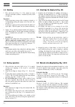
Страница 26: ...authorized switching over to another control mode take out key S5 after selecting the required mode See also section 3 1 5 3 5 Checking the display 4 Fig 3 5 1 Regularly check the display for readings and messages Normally the main display Fig 1 7 is shown indicating the compressor outlet pressure the interstage pressure the status of the compressor and the functions of the keys below the display ...

Страница 27: ...llation 7 Switch off the voltage Important After pressing stop button 9 the compressor will run unloaded for 30 seconds The compressor stops after this period A start command during this period is ignored After stopping the compressor is prevented from restarting within a programmable time 20 seconds A start command given during this minimum stop time will be memorized automatic operation LED 1 li...

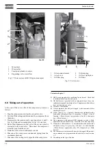
Страница 28: ...ressor is automatically started and stopped if these start stop commands are programmed and activated consult section 1 3 9 Depending on the type of button 1 Water inlet 2 Water outlet 3 Combined oil and air coolers 4 Regulating valve water flow Fig 3 7 Water system of GR W typical example 3 8 Taking out of operation At the end of the service life of the compressor proceed as follows 1 Stop the co...

Страница 29: ...rs 3 section below table Daily 3 5 7 1 Check readings on display Check that condensate is discharged during loading Monthly 200 9 If an OSD separator is provided check the oil level in the oil collector 3 monthly 5 3 Operate safety valve Remove dismantle and clean float valve of condensate trap s Clean compressor 4 Check for possible leaks 500 5 2 Check coolers clean if necessary 500 5 1 1 Remove ...

Страница 30: ...densate trap fill the new filter with water and fit it Inspect the strainer restrictor at the inlet of the separator vessel clean and reinstall it Close the valve underneath the condensate trap 4 2 Motors 4 2 1 Fan motors on GR GR132 up to GR200 have two fan motors M25 26 Fig 1 3 GR110 has one fan motor The bearings of the motors must be replaced after 24 000 operating hours 4 2 2 Drive motor M1 F...

Страница 31: ...lean the filter seats on the manifold Oil the gaskets of the new filters and screw them into place until the gaskets contact their seats then tighten by hand 4 Tighten filler plug 3 Fig 3 8 5 Reset the oil filter service warning using key Reset in submenu Service 4 4 6 Storage after installation Run the compressor e g twice a week until warm Load and unload the compressor a few times to operate th...

Страница 32: ...ywork to separate the major part of the oil from the condensate The condensate meets the requirements of the environmental codes The system includes an OSD315 oil water separator connected to the condensate trap downstream of the air cooler The condensate is led from the condensate trap through inlet 4 and filter 5 towards water vessel 3 where the oil rises due to the difference in specific mass T...

Страница 33: ...ction Submenu STATUS DATA 4 Condensate is not discharged from condensate trap s during loading a Discharge pipe of condensate trap clogged a Check and correct as necessary b Float valve of condensate trap s malfunctioning b Remove float valve assembly clean and check 5 Compressor air delivery or pressure below normal a Air consumption exceeds air delivery of compressor a Check equipment connected ...

Страница 34: ...r GR Approx 29 C for GR Full feature Approx 26 C for GR W Approx 25 C for GR W Full feature Approx 22 C Compressor element 1 outlet temperature Between 80 and 100 C Compressor element 2 outlet temperature Between 90 and 110 C Cooling air inlet temperature on GR Below 40 C Cooling water temperature on GR W Below 50 C Pressure dewpoint GR Full feature Approx 3 C 1 Pressure drop over DD filter option...

Страница 35: ... 2 Motor overload relay and fuses for 60 Hz IEC compressors GR GR W Motor type ABB Supply Max setting of Max fuse ratings Class gL gG voltage overload relay F21 Type 2 2 Type 1 3 V A A A 110 M2CA 315SMA 4 220 230 257 2x 3x300 3x500 110 M2CA 315SMA 4 380 149 3x250 3x400 110 M2CA 315SMA 4 440 460 129 3x224 3x400 160 M2CA 315 MB 4 380 195 2x 3x250 3x400 160 M2CA 315 MB 4 440 460 169 3x250 3x400 200 M...

Страница 36: ...GR200 60 380 Q25 26 11 7 Cooling fan for air and oil coolers GR200 60 440 460 Q25 26 9 9 Cooling fan for air and oil coolers GR200 60 575 Q25 26 7 7 Bodywork ventilation fan GR110 200 W 50 230 Q25 2 5 Bodywork ventilation fan GR110 200 W 50 400 Q25 1 4 Bodywork ventilation fan GR110 200 W 50 500 Q25 1 1 Bodywork ventilation fan GR110 200 W 60 220 230 Q25 2 1 Bodywork ventilation fan GR110 200 W 60...

Страница 37: ...0 1 9 GR110 160 dryer cooling fan motor 60 575 1 4 GR200 dryer cooling fan motor 60 380 8 8 GR200 dryer cooling fan motor 60 440 460 7 7 GR200 dryer cooling fan motor 60 575 5 9 7 4 7 Circuit breaker for control circuit Q1 Type Frequency Supply Transfo Transfo Transfo Transfo voltage T1 250 VA T1 400 VA T1 630 VA T1 800 VA Hz V A A A A GR110 160 50 230 1 5 2 4 3 6 4 5 GR110 160 50 400 0 9 1 4 2 2 ...

Страница 38: ... working pressure bar e 13 13 13 13 Maximum working pressure Full feature bar e 12 75 12 75 12 75 12 75 Maximum working pressure Full feature with DD filter bar e 12 4 12 4 12 4 12 4 Nominal working pressure bar e 12 5 12 5 12 5 12 5 Nominal working pressure Full feature with DD filter bar e 12 4 12 4 12 4 12 4 Motor shaft speed r min 1487 1487 1487 1487 Power input GR 5 6 kW 122 149 177 209 Power...

Страница 39: ...essor type 110 160 200 Maximum working pressure bar e 13 8 13 8 13 8 Maximum working pressure Full feature bar e 13 55 13 55 13 55 Maximum working pressure Full feature with DD filter bar e 13 2 13 2 13 2 Nominal working pressure bar e 13 3 13 3 13 3 Nominal working pressure Full feature with DD filter bar e 13 2 13 2 13 2 Motor shaft speed r min 1790 1789 1788 Power input GR 5 6 kW 141 188 238 Po...

Страница 40: ...units 1 bar 14 504 psi 1 g 0 035 oz 1 kg 2 205 lb 1 kW 1 341 hp UK and US 1 l 0 264 US gal 1 l 0 220 Imp gal UK 1 l 0 035 cu ft 1 l s 2 117 cfm 1 mm 0 039 in 1 mbar 0 401 in water column 1 N 0 225 lbf 1 Nm 0 738 lbf ft x C 32 1 8 x F 10 Footnotes chapter 7 1 At ambient of 20 C and 80 relative humidity 2 No damage will occur at the overload relay 3 Disturbance or destruction of the contactor and or...

Отзывы: