2920 1449 00
31
Instruction book
4.4 Oil change
1. Run the compressor until warm. Stop the compressor and
switch off the voltage. Wait a few minutes and depressurize
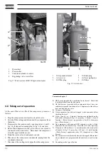
by unscrewing plug (3-Fig. 3.8) only one turn to permit any
pressure in the system to escape.
2. On GR, loosen vent plugs (5-Fig. 1.2) on top of the coolers.
3. Drain the oil by removing the drain plugs. Plugs are
provided on the air receiver (4-Fig. 3.8), oil stop valve (4-
Fig. 4.1), check valve (6-Fig. 4.1), oil coolers and gearbox
(2-Fig. 4.1). Tighten the plugs after draining.
4. Remove filler plug (3-Fig. 3.8). Fill the air receiver with
oil until the level reaches the filler opening. Reinstall and
tighten plug (3-Fig. 3.8). Tighten the vent plugs (5-Fig.
1.2).
5. Run the compressor loaded for a few minutes to allow the
oil cooler by-pass valve to open. Stop the compressor and
wait a few minutes.
6. Depressurize the system by unscrewing plug (3-Fig. 3.8)
only one turn to permit any pressure in the system to escape.
Remove the plug. Fill the air receiver with oil until the
level reaches the filler opening. Tighten plug (3-Fig. 3.8).
7. Reset the oil service warning using key <<Reset>> in
submenu <<Service>>. 4)
4.5 Oil filter change
1. Stop the compressor, switch off the voltage and depressurize
by unscrewing plug (3-Fig. 3.8) only one turn to permit any
pressure in the system to escape.
2. Provide an oil pan to avoid possible oil spilling. Remove
oil filters (6-Fig. 3.8).
3. Clean the filter seats on the manifold. Oil the gaskets of the
new filters and screw them into place until the gaskets
contact their seats, then tighten by hand.
4. Tighten filler plug (3-Fig. 3.8).
5. Reset the oil filter service warning using key <<Reset>> in
submenu <<Service>>. 4)
4.6 Storage after installation
Run the compressor, e.g. twice a week, until warm. Load and
unload the compressor a few times to operate the components
of the unloading/loading system.
If the compressor is going to be stored without running from
time to time, protective measures must be taken. Consult Atlas
Copco.
4.7 Service kits
Service kits
Service kits comprise all parts needed for servicing components
and offer the benefits of genuine Atlas Copco parts while
keeping the maintenance budget low. All service kits are
mentioned in the relevant Parts Lists.
Atlas Copco HD Roto-injectfluid
Atlas Copco HD Roto-injectfluid (see section 4.3) can be
ordered in following quantities:
Quantity
Ordering number
20-litre can
2901 0572 01
209-litre drum
2901 0572 02
Footnotes chapter 4
1) On compressors with optional OSD separator, a valve is fitted
underneath the condensate trap. Close the valve after repairing.
2) Use only authorized parts. Any damage or malfunction caused
by the use of unauthorized parts is not covered by Warranty or
Product Liability.
3) Whichever interval comes first. The local Atlas Copco Sales
Company may overrule the maintenance schedule, especially the
service intervals, depending on the environmental and working
conditions of the compressor.
4) See "User manual for Elektronikon regulator", section "Submenu
SERVICE".
Содержание GR110
Страница 6: ...2920 1449 00 6 Instruction book Fig 1 4 GR Full feature during unloading ...
Страница 7: ...2920 1449 00 7 Instruction book Fig 1 5 GR Full feature during loading ...
Страница 14: ...2920 1449 00 14 Instruction book Fig 2 2 Dimension drawing GR110 W up to GR200 W ...
Страница 15: ...2920 1449 00 15 Instruction book Fig 2 3 Installation proposal 2 2 Installation proposals Fig 2 3 ...


