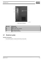
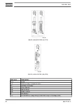
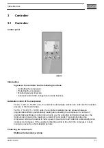


Reference
Designation
1x3
Terminal block of earth protection
1x5
Terminal block of control unit
Electrical diagram
2205 0161 00
Service diagram G 2 – G 3 – G 4 DOL IEC
2205 0161 50
Service diagram G 4 – G 5 – G 7 YD IEC
2205 0347 00
Service diagram G 2 – G 4 – G 5 – G 7 DOL UL
2205 0347 50
Service diagram G 2 – G 4 – G 5 – G 7 DOL CSA
The complete electrical diagram can be found in the electric cubicle.
The complete electrical diagram can be found on the USB supplied with the machine.
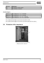
2.8
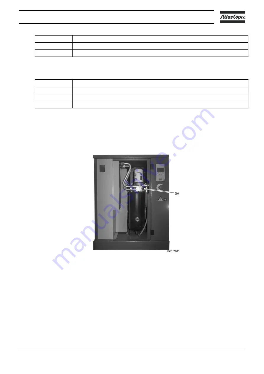
Protection of the compressor
Safety valve on the compressor
Instruction book
2920 7199 10
25
Содержание G 2
Страница 1: ...INSTRUCTION BOOK OIL INJECTED ROTARY SCREW COMPRESSORS G 2 G 3 G 4 G 5 G 7 ...
Страница 2: ......
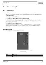
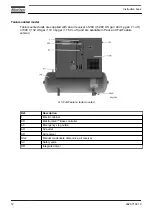
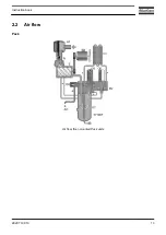
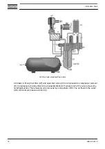
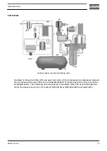
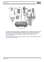
Страница 15: ...2 2 Air flow Pack Air flow floor mounted Pack units Instruction book 2920 7199 10 13 ...
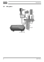
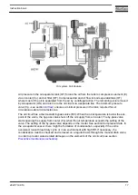
Страница 18: ...2 3 Oil system Oil system Pack Instruction book 16 2920 7199 10 ...
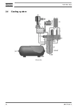
Страница 20: ...2 4 Cooling system Pack units Instruction book 18 2920 7199 10 ...
Страница 60: ...Start up Start up sheet Label on the top Instruction book 58 2920 7199 10 ...
Страница 92: ......
Страница 93: ......


