


Manual & Parts Lists Technical
15
General Machine Adjustments
Air Pressure
Set all air supply pressure regulators (Right to left):
Main Pressure:
70 PSI
Puller Pressure:
30 PSI
Ruffle Blade Pressure:
10 PSI
Foot Sew Pressure:
15 PSI
Sewing Head
See the manufacturer’s manuals for normal adjustments and parts. The presser
foot spring pressure should be set very light so that the ruffling blade can feed under the
foot while ruffling. The Efka motor should be set for stopping needle down at neutral
treadle to help hold the ruffle in place while turning the corners. The auxiliary foot
pressure cylinder should be set to provide added foot pressure while sewing straight.
Ruffler Drive
Set the Ruffler blade position left to right. The slot in the Ruffler blade should align
with the sewing needle. Loosen the 4 clamp screws and adjust ruffler blade left or right as
needed.
Set the Ruffler blade IN position so that the front edge of the blade is even with the
needle when the ruffler drive is positioned at the IN sensor. To position the drive at the
sensor, press the manual ruffle button once and quickly tap the treadle or sew pedal. The
Ruffler should position itself at the IN sensor. Adjust the sensor position in its slot, press
the manual ruffle button to reset the ruffler and repeat the cycle to test the setting.
Set the Ruffler blade OUT position by turning the adjusting knob on the front cover
of the ruffler drive. This controls how big each ruffle will be. After making an adjustment,
always reset the ruffler by pressing the manual ruffle button twice.
The swing-out stripper blade protects the panel from the ruffler blade while ruffling
so that the panel does not get pleated by the blade. It should be positioned as close to the
presser foot as possible. The ruffling air pressure should be set as high as practical
without it pressing the stripper blade down and pinching the panel while turning.
Puller Drive
Set the puller down position as low as practical without actually touching the cloth
plate. The roller should be centered on the needle. Set the Puller air pressure as needed
to provide positive feeding without the puller stalling at high speed.
Unwinder Assembly
The Unwinder is belt driven from a right angle gear motor. The motor and bearings
are permanently lubricated and require no regular maintenance. Check the belt tension
periodically and adjust if necessary. Check the gear pulley and bearing set screws for
tightness. The electric eye mounted on the guide rod should be set to "see" the gusset
material before the loop is entirely used up.
Содержание 1335MF
Страница 2: ......
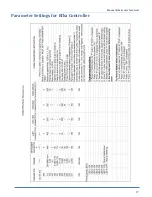
Страница 23: ...Manual Parts Lists Technical 17 Parameter Settings for Efka Controller ...
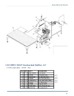
Страница 24: ...Technical Manual Parts Lists 18 1335M Folder Spacer Reference Chart ...
Страница 34: ...Technical Manual Parts Lists 28 ...
Страница 36: ...Technical Manual Parts Lists 30 ...
Страница 44: ...Technical Manual Parts Lists 38 ...
Страница 48: ...Technical Manual Parts Lists 42 ...
Страница 50: ...Technical Manual Parts Lists 44 ...
Страница 52: ...Technical Manual Parts Lists 46 ...
Страница 54: ...Technical Manual Parts Lists 48 ...
Страница 56: ...Technical Manual Parts Lists 50 ...
Страница 60: ...Technical Manual Parts Lists 54 ...
Страница 68: ...Technical Manual Parts Lists 62 ...
Страница 70: ...Technical Manual Parts Lists 64 ...
Страница 72: ...Technical Manual Parts Lists 66 ...
Страница 78: ...Technical Manual Parts Lists 72 1335MF PD Pneumatic Diagram 125860A ...
Страница 79: ...Manual Parts Lists Technical 73 1959 PD Pneumatic Diagram 125492C ...
Страница 80: ...Technical Manual Parts Lists 74 1334S 01WD Wiring Diagram 125627C ...
Страница 81: ...Manual Parts Lists Technical 75 1334S 02WD Wiring Diagram 125690C ...
Страница 82: ...Technical Manual Parts Lists 76 1335MF WD Wiring Diagram 125665C ...
Страница 83: ...Manual Parts Lists Technical 77 1335MFC 34WD2 Wiring Diagram 125712C ...


