


Technical Manual & Parts Lists
14
Sewing the Panel with Straight Corners
Set thumbwheel #5 to "7" for 1 ruffle per side, “8” for 2 ruffles per side, or "9" for 3
ruffles per side. Sew the panel to the corner being sure not to get your hands in the way
of the electric eye mounted under the table, which must "see" the edge of the panel as it
nears the presser foot. The machine will pause momentarily as the ruffler engages and
then continue to sew straight as it makes the ruffles.
After the last ruffle is finished on the first side of the corner the machine will
continue to sew slow stitches based on the setting of thumbwheel #1. The number of slow
stitches sewn is equal to twice the setting of thumbwheel #1. Setting the thumbwheel to
“0” will disable this slow sew function. After the slow stitches the machine will stop with
the presser foot lifted. Turn the panel 90 degrees. Release and depress the treadle. The
foot will drop and the machine will again make slow stitches based on the setting of
thumbwheel #1, and then begin making the ruffles on the second side of the corner.
When the ruffles are complete the machine will resume sewing at treadle speed. Adjust
the stop count as necessary to achieve the desired corner finish.
Adjusting the Corner Ruffles
The ruffles should be set so the outer edge of the gusset lays flat for taping. A
typical ruffled gusset will have ruffles which butt against each other without overlapping
or gaps between them. Adjust Thumbwheels #5 and #6 and the ruffle size knob to
achieve the desired finish. Euro style gussets typically have 3 or 4 small ruffles with extra
stitches between them.
Finishing the Panel
After the last corner, sew the panel until the starting edge of the gusset is almost to
the presser foot. Stop and activate the “Wipe” switch to raise the folder. Cut the gusset so
that there is enough overlap of gusset for finishing. Swing out the stripper blade. Fold the
trailing edge of the gusset under itself, lay it on top of the starting edge and oversew the
two together. Heal back and remove the panel. Reload the gusset under the foot and
puller and lower the folder. Note: The automatic functions will not operate with the folder
up!
Efka Control Box Settings
The Efka control has been preprogrammed to operate the sewing head in
conjunction with the ruffler. The maximum sewing speed has been preset to 4000 RPM.
The maximum sewing speed can be temporarily reduced by holding in the "-" button on
front of the control box while sewing. To restore maximum speed use the "+" button. Be
sure the needle down LED is the only LED lit on front of the control box. The LED's can be
changed only immediately after power on or a full healback. Refer to the appendix for
complete Efka programming parameters.
Содержание 1335MF
Страница 2: ......
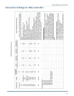
Страница 23: ...Manual Parts Lists Technical 17 Parameter Settings for Efka Controller ...
Страница 24: ...Technical Manual Parts Lists 18 1335M Folder Spacer Reference Chart ...
Страница 34: ...Technical Manual Parts Lists 28 ...
Страница 36: ...Technical Manual Parts Lists 30 ...
Страница 44: ...Technical Manual Parts Lists 38 ...
Страница 48: ...Technical Manual Parts Lists 42 ...
Страница 50: ...Technical Manual Parts Lists 44 ...
Страница 52: ...Technical Manual Parts Lists 46 ...
Страница 54: ...Technical Manual Parts Lists 48 ...
Страница 56: ...Technical Manual Parts Lists 50 ...
Страница 60: ...Technical Manual Parts Lists 54 ...
Страница 68: ...Technical Manual Parts Lists 62 ...
Страница 70: ...Technical Manual Parts Lists 64 ...
Страница 72: ...Technical Manual Parts Lists 66 ...
Страница 78: ...Technical Manual Parts Lists 72 1335MF PD Pneumatic Diagram 125860A ...
Страница 79: ...Manual Parts Lists Technical 73 1959 PD Pneumatic Diagram 125492C ...
Страница 80: ...Technical Manual Parts Lists 74 1334S 01WD Wiring Diagram 125627C ...
Страница 81: ...Manual Parts Lists Technical 75 1334S 02WD Wiring Diagram 125690C ...
Страница 82: ...Technical Manual Parts Lists 76 1335MF WD Wiring Diagram 125665C ...
Страница 83: ...Manual Parts Lists Technical 77 1335MFC 34WD2 Wiring Diagram 125712C ...


