background image

www.atestgaz.pl

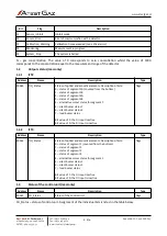
10.2.2

PW-089-C-X

PW-089-C-

-

-

-

-

   Segment 1

   Segment 2

   Segment 3

R

Red 

MR

Blinking red

G

Green

MG

Blinking green

B

Blue

MB

Blinking blue

Y

Yellow

MY

Blinking yellow

W

White

MW

Blinking white

   Segment 4

R

Red 

MR

Blinking red

RFR

Red with flash light

MRFR

Blinking red with flash light

G

Green

MG

Blinking green

B

Blue

MB

Blinking blue

Y

Yellow

MY

Blinking yellow

YFY

Yellow with flash light

MYFY

Blinking yellow with flash light

W

White

MW

Blinking white

   Cable gland

X

See details in POD-066-ENG „Cable glands used in offered devices”

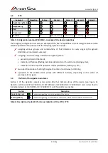
Table 12: Configuration of PW-089-C-X version

11

Appendices

[1]

DEZG115-ENG – EU Declaration of Conformity – LTT2 / LTT4

[2]

PU-Z-096-ENG – The memory map for the GTW functionality in LTT2 and LTT4

s. 23|23

User Manual: POD-037-ENG R06

S1 S2 S3 S4 G

S1

S2

S3

S4

G

Содержание LTT2

Страница 1: ...POD 037 ENG R06 User Manual Warning LED Tower with Sounder LTT2 LTT4 Product code PW 091 X PW 089 X...

Страница 2: ...Monitoring Detection and Reduction of gas hazards For more details please visit our website www atestgaz pl Atest Gaz A M Pachole sp j ul Spokojna 3 44 109 Gliwice Poland tel 48 32 238 87 94 fax 48 3...

Страница 3: ...uarded may need consideration of other requirements during the entire lifetime of the product How to use this manual The following symbols of optical indicators status are used throughout the document...

Страница 4: ...ng 21 10 1 LTT2 Warning LED Tower with Sounder 21 10 2 LTT4 Warning LED Tower with Sounder 22 11 Appendices 23 List of Tables Table 1 Optical indicators status notation 3 Table 2 Electric connections...

Страница 5: ...M X 12 Figure 6 Device with Modbus interface control PW 091 M X PW 089 M X 12 Figure 7 Installation of the device step 1 15 Figure 8 Installation of the device step 2 15 Figure 9 Installation of the d...

Страница 6: ...o warn about specific events in various systems for gas detection to raise alarms under emergency conditions or other safety infringements in industrial facilities Figure 1 Location and role of the LT...

Страница 7: ...orse than the device see Table 8 appropriate mounting thread see Table 8 Details see Chapter 9 1 3 1 Replacement of cable gland To replace screw the cable gland remove the gland from device if it is s...

Страница 8: ...put interfaces 4 1 Electrical interface Figure 3 Electric connections s 8 23 User Manual POD 037 ENG R06 I II III SA SB EA EB connection diagram for RS485 Sigma Gas or Modbus system A 1 2 3 4 connecti...

Страница 9: ...the acoustic signaller Applying the supply voltage to the pin activates the acoustic signalling 3 1 Control and signalling input of the 1 LED segment Applying the supply voltage to the pin activates t...

Страница 10: ...ual detector s or the entire monitoring system indication of other specific operation modes calibration heating up etc two operation modes of each light segment solid on continuous or blinking operati...

Страница 11: ...al POD 037 ENG R06 8 PK 4 DI 1 32 SmArtGas 4 detectors 8 4 20 mA 8 PK 4 DI SBUS EBUS RS 485 MODBUS ASCII RTU Ethernet MODBUS TCP Profibus NOTE The diagram presents merely an example of the system layo...

Страница 12: ...ices 2 The signaller subsystems are turned on according to logic shown on the Figure 6 Figure 6 Device with Modbus interface control PW 091 M X PW 089 M X s 12 23 User Manual POD 037 ENG R06 Buzzer co...

Страница 13: ...the original package or another protecting means e g corks is unavailable the conveyed equipment must be secured against shocks vibrations or moisture by means of adequate methods and material at the...

Страница 14: ...agnetic interferences 8 2 1 List of tools necessary for installation of the signaller Denomination Tool N1 Allen socket wrench 2 5 mm with a ball tip N2 Open end flat spanner 22 mm Table 7 List of too...

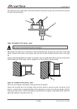
Страница 15: ...ct power voltage and control lines to the signaller use the N1 tool to loose four bolts that secure the cover of the cable connector Figure 8 Installation of the device step 2 s 15 23 User Manual POD...

Страница 16: ...a hanger The signaller must be installed from the top moving it downwards and the upper part of the hanger must be engaged in the top deck of the device housing Figure 10 Installation of the device s...

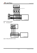
Страница 17: ...1 M X PW 089 M X For the PW 091 S X PW 089 S X and PW 091 M X PW 089 M X device wiring is recommended by means of shielded twisted cables The wiring diagram is shown on the figure below Figure 12 One...

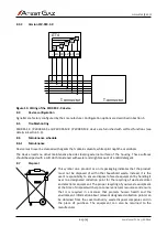
Страница 18: ...Two wires connection 8 3 2 Version PW 091 C X Figure 14 Wiring of the PW 091 C X device s 18 23 User Manual POD 037 ENG R06 2 1 A LTT2 T connector T connector EB EA SB SA T connector LTT2 LTT4 Unconn...

Страница 19: ...and slight amount of a mild detergent 8 7 Disposal This symbol on a product or on its packaging indicates that the product must not be disposed of with other household waste Instead it is the user s...

Страница 20: ...Deactivated Activated 0 1 V 18 30 V Integrated signalling equipment optical LED lamps Integrated signalling equipment acoustic Level 1 70 dB from 1 m Level 2 90 dB from 1 m Modulation and flash time...

Страница 21: ...cable gland X See details in POD 066 ENG Cable glands used in offered devices Table 9 Configuration of PW 091 S X PW 091 M X version 10 1 2 PW 091 C X PW 091 C Segment 1 R Red MR Blinking red G Green...

Страница 22: ...r 10 2 1 PW 089 S X PW 089 M X PW 089 Interface S Sigma M Modbus Segment 1 R Red RG Red green G Green B Blue Y Yellow YG Yellow green W White Segment 2 Segment 3 R Red G Green B Blue Y Yellow W White...

Страница 23: ...reen MG Blinking green B Blue MB Blinking blue Y Yellow MY Blinking yellow YFY Yellow with flash light MYFY Blinking yellow with flash light W White MW Blinking white Cable gland X See details in POD...

Страница 24: ...2010 in relation to Directive 2014 30 EU on the harmonisation of the laws of the Member States relating to electromagnetic compatibility EN 50270 2015 In relation to directive 2011 65 EU on the restri...

Страница 25: ...or status flags 40064 N Output signal concentration U16 State_A status of a detector at the specific channel Assignment of the individual bits is listed in the table below Bit Flag Description 0 Colle...

Страница 26: ...status 1 6 silent buzzer status 2 7 loud buzzer status Bit value of 1 the DI input is active Bit value of 0 the DI input is inactive flags 1 2 2 LTT4 Address Name Description Type 40065 DO_Status Stat...

Страница 27: ...inputs pulse edge controlled Write 1 the previous status of 0 generates a single pulse at the selected input Write 1 the previous status of 1 no action Write 0 the input remains unaltered the previous...

Страница 28: ...15 Unused 1 6 2 LTT4 Bit Flag Description 0 Seg_1 Segment 1 1 Seg_2 Segment 2 2 Seg_3 Segment 3 only for LTT4 3 Seg_4 Segment 4 only for LTT4 4 Seg_1_Alt Segment 1 alternative colour 5 Acoustic_L_1 Qu...

Страница 29: ...www atestgaz pl Notes...

Страница 30: ...www atestgaz pl Notes...

Страница 31: ......

Страница 32: ...M Pachole sp j Spokojna 3 44 109 Gliwice tel 48 32 238 87 94 fax 48 32 234 92 71 e mail contact atestgaz pl For more details on our devices and other products and services offered by us visit www ate...

Отзывы: