www.atestgaz.pl
5.2
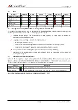
LTT4
Segment
Operation
Failure
Alarm I
Alarm II
Alarm III
Alarm IV
4 Red/blinking/flash
3 Red/blinking
2 Red
1 Green/red
- Sounder
off
off
Reduced intensity
Full intensity
Full intensity
Full intensity
Table 5: Configuration example PW-089-X – meaning of the device indications
The foregoing configuration is merely an example of the device capabilities since its design features enable
versatile operation of the device with the following operation modes:
assigning various groups and combinations of field detectors to every single light segment
(definition of monitored sub-areas)
assigning various warnings and alarms to light segments:
•
exceeding of alarm thresholds,
•
indication of failures affecting individual detector(s) or the entire monitoring system,
•
indication of other specific operation modes (calibration, heating up, etc.)
two operation modes of each light segment: solid-on (continuous) or blinking,
operation of the audible alarm (siren) with different intensity, depending on the status of
warning /alarm signals.
5.3
The field of the signaller own states
Section 1 of the signaller comprises two pilot LEDs that indicate status of the device (see Figure 2).
Operation of these LEDs for PW-091-S-X / PW-089-S-X and PW-091-M-X / PW-089-M-X units is described in
the table below. For the PW-091-C-X / PW-089-C-X unit these LEDs are inactive.
Controls
Description
Operation (green)
Continuous signalling – correct operation of the device
Failure (yellow)
Continuous signalling – critical failure of the device, please contact with the manufacturer
Table 6: Description of pilot LED for status indication of the LTT2 / LTT4
s. 10|23
User Manual: POD-037-ENG R06
Содержание LTT2
Страница 1: ...POD 037 ENG R06 User Manual Warning LED Tower with Sounder LTT2 LTT4 Product code PW 091 X PW 089 X...
Страница 29: ...www atestgaz pl Notes...
Страница 30: ...www atestgaz pl Notes...
Страница 31: ......


