www.atestgaz.pl
List of Figures
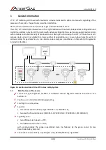
Figure 1: Location and role of the LTT2 in Gas Safety System.....................................................................................6
Figure 2: Layout of device components and its dimensions.......................................................................................8
Figure 3: Electric connections................................................................................................................................... 8
Figure 4: Architecture with signaller PW-091-S -X / PW-089-S-X...............................................................................11
Figure 5: Architecture with signaller PW-091-M-X / PW-089-M-X............................................................................12
Figure 6: Device with Modbus interface control (PW-091-M-X / PW-089-M-X).........................................................12
Figure 7: Installation of the device – step 1.............................................................................................................15
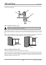
Figure 8: Installation of the device – step 2.............................................................................................................15
Figure 9: Installation of the device – step 3.............................................................................................................16
Figure 10: Installation of the device – step 4............................................................................................................16
Figure 11: Installation of the device – step 5............................................................................................................17
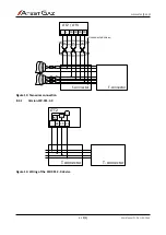
Figure 12: One wire connection.............................................................................................................................. 17
Figure 13: Two wires connection............................................................................................................................. 18
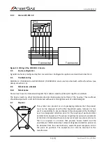
Figure 14: Wiring of the PW-091-C-X device............................................................................................................18
Figure 15: Wiring of the PW-089-C-X device............................................................................................................19
s. 5|23
User Manual: POD-037-ENG R06
Содержание LTT2
Страница 1: ...POD 037 ENG R06 User Manual Warning LED Tower with Sounder LTT2 LTT4 Product code PW 091 X PW 089 X...
Страница 29: ...www atestgaz pl Notes...
Страница 30: ...www atestgaz pl Notes...
Страница 31: ......


