www.atestgaz.pl
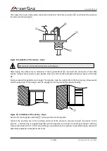
Figure 7: Installation of the device – step 1
To connect power voltage and control lines to the signaller use the N1 tool to loose four bolts ② that
secure the cover of the cable connector ③.
Figure 8: Installation of the device – step 2
s. 15|23
User Manual: POD-037-ENG R06
②
②
③
⑤
⑦
⑧
120 mm (LTT2)
240 mm (LTT4)
①
max. 7mm
Φ max. 5mm
Φ: 5.5 mm
Φ max. 10mm
Содержание LTT2
Страница 1: ...POD 037 ENG R06 User Manual Warning LED Tower with Sounder LTT2 LTT4 Product code PW 091 X PW 089 X...
Страница 29: ...www atestgaz pl Notes...
Страница 30: ...www atestgaz pl Notes...
Страница 31: ......


