


7-1
7. Radiator/Oil Cooler
Disassembly and Assembly
Chapter Overview
This chapter provides disassembly and assembly
procedures for the radiator/oil cooler assembly.
Personal Safety
! WARNING !
Improper operation, lubrication, maintenance or repair
of this product can be dangerous and could result in
injury or death.
Do not operate or perform any lubrication, mainte-
nance or repair on this product until you have read
and understood the operation, lubrication, mainte-
nance and repair information.
Machine Preparation
! WARNING !
Accidental machine starting can cause injury or death
to personnel working on the machine.
To avoid accidental machine starting, disconnect the
battery cables from the battery and tape the battery
clamps and remove the key.
Place a “Do Not Operate” tag prominently on the ma-
chine to inform personnel that the machine is being
worked on.
Before starting any disassembly or assembly proce-
dures, refer to
Chapter 2. Product Safety – Repair
for machine preparation information.
Preliminary Checkout
If troubleshooting is required prior to disassembly or
assembly, refer to
Chapter 13. Troubleshooting
.
Radiator/Oil Cooler
Disassembly and Assembly
Procedures
Disassembly and assembly procedures are provided
for the following radiator/oil cooler components.
•
Fan Guard
•
Fan
•
Air Conditioning Condenser (if equipped)
•
Radiator/Oil Cooler
Note:
Procedures are provided for only those radiator/oil
cooler components listed above. However, information for
removal and installation of other radiator/oil cooler compo-
nents can be obtained from the Rubber Track Loader
Parts List manual.
Note:
Refer to Figure 3-1 for an overview of the filtering
and cooling system.
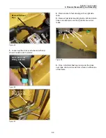
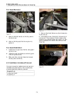
Fan Guard Removal and In-
stallation
The tools required for fan guard removal and instal-
lations are listed below. Use manufacturer-
recommended tools whenever possible.
Required Tools
Combination Wrench
Содержание RC-100
Страница 2: ......
Страница 10: ......
Страница 12: ......
Страница 14: ...Rubber Track Loader 3 System Diagrams 3 2 Auxiliary Circuit System Figure 3 2 RC 100 Auxiliary Circuit System ...
Страница 15: ...Rubber Track Loader 3 System Diagrams 3 3 Drive Loop System Figure 3 3 RC 100 Drive Loop System ...
Страница 16: ...Rubber Track Loader 3 Systems Diagrams 3 4 Loader Valve Figure 3 4 RC 100 Loader Valve ...
Страница 30: ......
Страница 36: ......
Страница 46: ......
Страница 56: ......
Страница 68: ...Terex Construction Americas 8800 Rostin Road Southaven MS 38671 888 201 6008 662 393 1800 www terex com ...