


Rubber Track Loader
5. Operator Enclosure Disassembly and Assembly
5-2
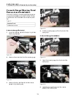
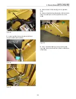
1.
Remove the two bolts that attach the light bar to
the cab frame. It may be necessary to remove a
side window if equipped with an enclosed cab.
Figure 5-2
2.
Carefully lower the light bar with the wire har-
ness attached.
Figure 5-3
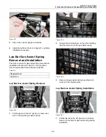
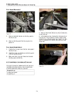
3.
View of light bar interior (to operator’s right when
seated). Interior components are now accessible
for servicing.
Figure 5-4
4.
View of light bar interior (to operator’s left when
seated).
Figure 5-5
Ignition Switch Removal and
Installation
The tools required for ignition switch removal and
installation are listed in Table 5-2. Use manufac-
turer-recommended tools whenever possible.
Table 5-2
Required Tools
Combination Wrench
Ignition Switch Removal
1.
Lower the light bar. Refer to
Chapter 5.
Light Bar
Removal
procedure.
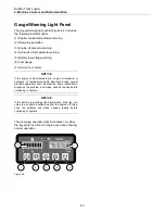
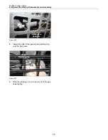
Headlights
Ignition
Switch
Console
Gauge
Aux. Hyd.
Switches
Two Speed
Inicator
Light
Switch
Power Quick-
Attach Switch
Содержание RC-100
Страница 2: ......
Страница 10: ......
Страница 12: ......
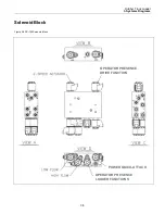
Страница 14: ...Rubber Track Loader 3 System Diagrams 3 2 Auxiliary Circuit System Figure 3 2 RC 100 Auxiliary Circuit System ...
Страница 15: ...Rubber Track Loader 3 System Diagrams 3 3 Drive Loop System Figure 3 3 RC 100 Drive Loop System ...
Страница 16: ...Rubber Track Loader 3 Systems Diagrams 3 4 Loader Valve Figure 3 4 RC 100 Loader Valve ...
Страница 30: ......
Страница 36: ......
Страница 46: ......
Страница 56: ......
Страница 68: ...Terex Construction Americas 8800 Rostin Road Southaven MS 38671 888 201 6008 662 393 1800 www terex com ...