background image

4-4

Chapter 4: Motherboard info

BIOS_WP

(Default)

FWP

.

WRITE ENABLE WRITE PROTECT

®

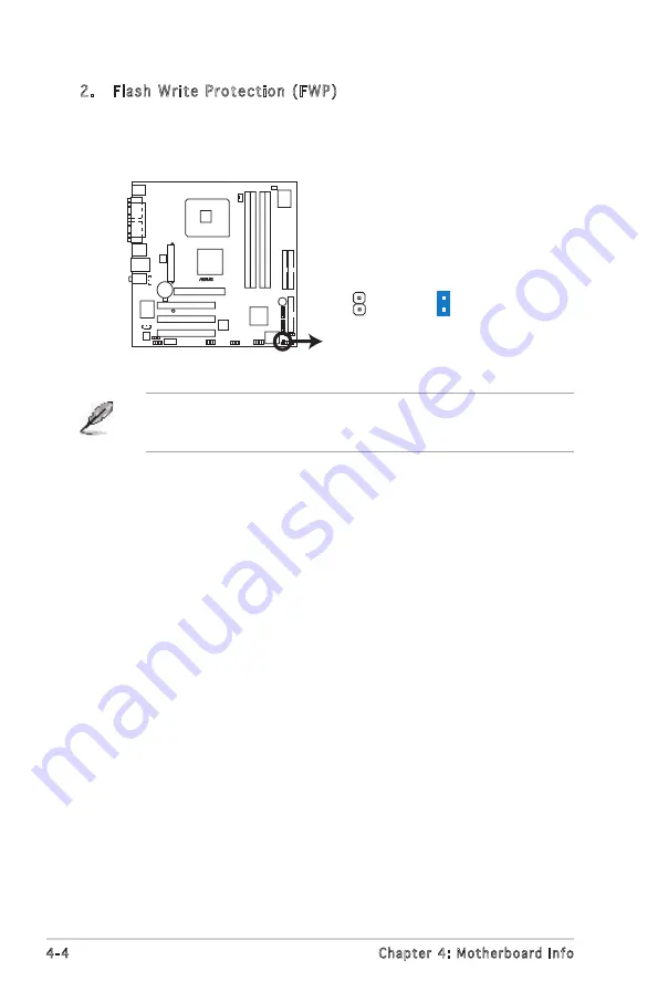
2.  Flash Write Protection (FWP)
 

Place the jumper cap on this jumper to write protect the BIOS. If you 

need to update your BIOS, remove the jumper cap. 

A warning message “Please make sure whether lockout jumper is set to 

correct or not.” appears when you flash the BIOS with the jumper cap. 

Remove the jumper cap before you update your BIOS.

Содержание Vintage V2-PE3

Страница 1: ...Vintage V2 PE3 PC Desktop Barebone ...

Страница 2: ...TICULAR PURPOSE IN NO EVENT SHALL ASUS ITS DIRECTORS OFFICERS EMPLOYEES OR AGENTS BE LIABLE FOR ANY INDIRECT SPECIAL INCIDENTAL OR CONSEQUENTIAL DAMAGES INCLUDING DAMAGES FOR LOSS OF PROFITS LOSS OF BUSINESS LOSS OF USE OR DATA INTERRUPTION OF BUSINESS AND THE LIKE EVEN IF ASUS HAS BEEN ADVISED OF THE POSSIBILITY OF SUCH DAMAGES ARISING FROM ANY DEFECT OR ERROR IN THIS MANUAL OR PRODUCT SPECIFICAT...

Страница 3: ...l Processing Unit CPU 2 4 2 4 1 Overview 2 4 2 4 2 Installing CPU 2 4 2 4 3 Installing the CPU fan and heatsink assembly 2 6 2 5 Installing a DIMM 2 8 2 5 1 Memory configurations 2 8 2 5 2 Installing a DIMM 2 11 2 5 3 Removing a DIMM 2 11 2 6 Expansion slots 2 12 2 6 1 Installing an expansion card 2 12 2 6 2 Configuring an expension card 2 12 2 6 3 AGP slot 2 14 2 6 4 PCI slots 2 14 2 7 Installing a...

Страница 4: ...otherboard layout 4 2 4 3 Jumpers 4 3 4 4 Connectors 4 5 Chapter 5 BIOS setup 5 1 Managing and updating your BIOS 5 2 5 1 1 Creating a bootable floppy disk 5 2 5 1 2 ASUS EZ Flash utility 5 3 5 1 3 Award BIOS Flash Uuility 5 3 5 1 4 Saving the current BIOS file 5 5 5 1 5 ASUS CrashFree BIOS 2 utility 5 6 5 2 BIOS setup program 5 7 5 3 BIOS menu screen 5 8 5 4 Standard BIOS features 5 10 5 5 Advanced...

Страница 5: ... harmful interference to radio or television reception which can be determined by turning the equipment off and on the user is encouraged to try to correct the interference by one or more of the following measures Reorient or relocate the receiving antenna Increase the separation between the equipment and receiver Connect the equipment to an outlet on a circuit different from that to which the rec...

Страница 6: ...contact your dealer immediately To avoid short circuits keep paper clips screws and staples away from connectors slots sockets and circuitry Avoid dust humidity and temperature extremes Do not place the product in any area where it may become wet Place the product on a stable surface If you encounter technical problems with the product contact a qualified service technician or your retailer Lithiu...

Страница 7: ... including introduction on the front and rear panel and internal components 2 Chapter 2 Basic installation This chapter provides step by step instructions on how to install components in the system 3 Chapter 3 Starting up This chapter helps you power up the system and install drivers and utilities from the support CD 4 Chapter 4 Motherboard information This chapter gives information about the moth...

Страница 8: ...bsites The ASUS websites worldwide provide updated information on ASUS hardware and software products Refer to the ASUS contact information 2 Optional Documentation Your product package may include optional documentation such as warranty flyers that may have been added by your dealer These documents are not part of the standard package System package contents Check your Vintage V2 PE3 system packag...

Страница 9: ...2 PE3 Chapter 1 System introduction This chapter gives a general description of the ASUS Vintage V2 PE3 The chapter lists the system features including introduction on the front and rear panel and internal components ...

Страница 10: ...ntium D Intel Pentium 4 or Intel Celeron processor in the 775 land package The system supports up to 2 GB of system memory using DDR 400 333 or DDR2 533 DIMMs high resolution graphics via integrated graphics controller or AGP slot Serial ATA USB 2 0 and 6 channel audio features the system takes you ahead in the world of power computing 1 2 Front panel The front panel includes the optical drive bay...

Страница 11: ...button to reboot the system without turning off the power 5 HDD LED This LED lights up when data is read from or written to the hard disk drive 6 USB 2 0 ports These Universal Serial Bus 2 0 USB 2 0 ports are available for connecting USB 2 0 devices such as a mouse printer scanner camera PDA and others 7 Headphone port This Line In green port connects a headphone with a stereo mini plug 8 Micropho...

Страница 12: ...his switch allows you to adjust the system input voltage according to the voltage supply in your area See the section Voltage selector on page 1 6 before adjusting this switch 3 PS 2 mouse port This green 6 pin connector is for a PS 2 mouse 4 PS 2 keyboard port This purple 6 pin connector is for a PS 2 keyboard 5 Serial port COM1 This port connects a mouse modem or other devices that conform with ...

Страница 13: ...e PSU fan that provides ventilation inside the power supply unit 13 Chassis fan vent This vent is for the fan that provides ventilation inside the system chassis 14 IEEE 1394a port This port provides high speed connectivity for IEEE 1394a compliant audio video devices storage peripherals and other PC devices 15 LAN RJ 45 port This port allows Gigabit connection to a Local Area Network LAN through ...

Страница 14: ...he appropriate system input voltage according to the voltage supply in your area If the voltage supply in your area is 100 127 V set this switch to 115 V If the voltage supply in your area is 200 240 V set this switch to 230 V Setting the switch to 115V in a 230V environment or 230V in a 115V environment will seriously damage the system 115V 230V Voltage selector ...

Страница 15: ... Chassis fan 10 AGP slot 11 PCI slots 12 Metal bracket lock 1 2 3 4 9 5 F_PANEL FWP CLRTC1 IR_CON LGA775 DDR2 DIMM_A1 128 bit 240 pin module DDR2 DIMM_B1 128 bit 240 pin module DDR DIMM_A1 64 bit 184 pin module DDR DIMM_B1 64 bit 184 pin module Super I O VIA VT837R Plus VIA P4M800 PRO AGP PCI1 PCI2 PCI3 RTL8100S 4Mb BIOS BUZZER CR2032 3V Lithium Cell CMOS Power ATXPWR ATX12V ALC655 PRI_IDE SEC_IDE...

Страница 16: ...1 8 Chapter 1 System introduction ...

Страница 17: ...ASUS Vintage V2 PE3 Chapter 2 Basic installation This chapter provides step by step instructions on how to install components in the system ...

Страница 18: ...t off mode and not powered OFF Unplug the power cable from the power outlet and make sure that the standby power LED is OFF before installing any system component Use a grounded wrist strap or touch a safely grounded object or a metal object such as the power supply case before handling components to avoid damaging them due to static electricity Hold components by the edges to avoid touching the I...

Страница 19: ...hooks disengage from the chassis tab holes Set the side cover aside 3 Locate the front panel assembly hooks then lift them until they disengage from the chassis 4 Swing the front panel assembly to the right until the hinge like tabs on the right side of the assembly are exposed 5 Remove the front panel assembly then set aside 1 1 2 2 4 3 4 4 3 3 Chassis tab holes Air duct 4 ...

Страница 20: ...ard components ASUS will shoulder the cost of repair only if the damage is shipment transit related Keep the cap after installing the motherboard ASUS will process Return Merchandise Authorization RMA requests only if the motherboard comes with the cap on the LGA775 socket The product warranty does not cover damage to the socket contacts resulting from incorrect CPU installation removal or misplac...

Страница 21: ... and forefinger to a 100º angle 4A then push the PnP cap from the load plate window to remove 4B 5 Position the CPU over the socket making sure that the gold triangle is on the bottom left corner of the socket then fit the socket alignment key into the CPU notch Gold triangle mark Alignment key CPU notch Load plate PnP cap 4A 4B 3 ...

Страница 22: ...rofessional medical help 2 4 3 Installing the CPU fan and heatsink assembly The Intel Pentium 4 LGA775 processor requires a specially designed heatsink and fan assembly to ensure optimum thermal condition and performance When you buy a boxed Intel Pentium 4 processor the package includes the CPU fan and heatsink assembly If you buy a CPU separately make sure that you use only Intel certified multi ...

Страница 23: ...lled CPU making sure that the four fasteners match the holes on the motherboard 3 When the fan and heatsink assembly is in place connect the CPU fan cable to the connector on the motherboard A B B 2 Push down two fasteners at a time in a diagonal sequence to secure the heatsink and fan assembly in place Do not forget to connect the CPU fan connector Hardware monitoring errors can occur if you fail...

Страница 24: ...ffered non ECC DDR DDR2 DIMMs into the DIMM sockets using the memory configurations in this section To prevent damage to the motherboard do not use DDR and DDR2 memory simultaneously Always install DIMMs with the same CAS latency For optimum compatibility we recommend that you obtain memory modules from the same vendor Refer to the DDR DDR2 Qualified Vendors List on the next page for details Due to ...

Страница 25: ...P512U648 C4 Hynix HY5PS12821F C4 1024Mbytes Unbuffer Hynix HYMP512U728 C4 ECC Hynix HY5PS12821F D4 1024Mbytes Unbuffer Micron MT16HTF12864AY 53EA1 Micron 4MAII D9CRZ 2048Mbytes Unbuffer Elpida EBE21EE8AAFA 5C E Elpida E1108AA 5C E 256Mbytes Unbuffer Albatron MDGVD5F3G31CB1EZ2 Vdata VDD8608A8A 5B 256Mbytes Unbuffer Apacer 73 85397 460 Samsung K4H560838D TCC4 256Mbytes Unbuffer Corsair CMX256A 3200L...

Страница 26: ...85C2256804SAT5B 512Mbytes Unbuffer Transcend TS64MLD64V4F PSC A2S56D30BTP 512Mbytes Unbuffer Weblink PW200411130 0447 Rami RS56D08BTP 5 512Mbytes Unbuffer Winbond W9451GBDB 5 Winbond W942508BH 5 512Mbytes Unbuffer Winbond U24512ADWBG6H20 Winbond W942508CH 5 1024Mbytes Unbuffer Transcend TS128MLD64V4J 1GB Samsung K4H510838C UCCC 256Mbytes Unbuffer Corsair VS256MB333 Samsung K4H560838D TBC3 256Mbyte...

Страница 27: ...seated 1 Unlock a DIMM socket by pressing the retaining clips outward 2 Align a DIMM on the socket such that the notch on the DIMM matches the break on the socket Locked Retaining Clip Make sure to unplug the power supply before adding or removing DIMMs or other system components Failure to do so may cause severe damage to both the motherboard and the components DDR DIMM notch 1 2 1 3 Unlocked ret...

Страница 28: ...use Keep the screw for later use 4 Align the card connector with the slot and press firmly until the card is completely seated on the slot 5 Secure the card to the chassis with the screw you removed earlier 6 Replace the system cover Make sure to unplug the power cord before adding or removing expansion cards Failure to do so may cause you physical injury and damage motherboard components 2 6 2 Con...

Страница 29: ...troller 7 15 Printer Port LPT1 8 3 System CMOS Real Time Clock 9 4 IRQ holder for PCI steering 10 5 IRQ holder for PCI steering 11 6 IRQ holder for PCI steering 12 7 PS 2 Compatible Mouse Port 13 8 Numeric Data Processor 14 9 Primary IDE Channel 15 10 Secondary IDE Channel These IRQs are usually available for ISA or PCI devices IRQ assignments for this motherboard A B C D E F G H PCI slot 1 shared...

Страница 30: ...all only 1 5 V or 0 8 V AGP cards on this motherboard 3 3V AGP cards are not supported in this motherboard 2 6 3 AGP slot The Accelerated Graphics Port AGP slot supports AGP8X 4X cards When you buy an AGP card make sure that you ask for one with 1 5V specification Note the notches on the card golden fingers to ensure that they fit the AGP slot on your motherboard The below figure shows a graphic card ...

Страница 31: ...5 25 inch drive bay and carefully push the optical drive into the bay until its screw holes align with the holes on the bay as shown 4 Secure the optical drive with two screws on both sides of the bay 4 4 3 IDE ribbon cable Power cable 5 Connect a power cable from the power supply to the power connector at the back of the optical drive 6 Connect one end of the IDE ribbon cable to the IDE interface...

Страница 32: ... Basic installation 7 Connect the other end of the IDE ribbon cable to the secondary IDE connector labeled SEC_IDE on the motherboard 8 Remove the dummy drive slot cover from the front panel 9 Replace the front panel ...

Страница 33: ... ATA or IDE hard disk drive s To install a Serial ATA hard disk drive 4 Secure the drive with two screws on both sides 4 4 3 1 Place the chassis upright 2 Use a screw driver to remove the HDD drive slot metal plate cover 3 With the HDD label side up carefully insert the drive into the 3 5 inch bay and push the drive into the bay until its screw holes align with the holes on the drive bay ...

Страница 34: ... becoming unstable 5 Connect one end of the Serial ATA cable to the SATA connector at the back of the drive then connect the other end to a Serial ATA connector on the motherboard 6 Connect a 15 pin Serial ATA power plug from the power supply unit to the 15 pin power connector at the back of the drive OR Connect a 4 pin female power plug from the power supply unit to the 4 pin male power connector...

Страница 35: ...the IDE cable and power plug Refer to the HDD documentation on how to set the drive as a Master device If you will install two IDE hard disk drives configure the other device as Slave 3 Connect the gray interface of the IDE ribbon cable to the IDE connector on the drive 4 If you install two IDE hard disk drives connect the black interface of the IDE ribbon cable to the IDE connector on the second S...

Страница 36: ...t the floppy disk drive into the floppy drive bay until the screw holes align with the holes on the bay 3 Secure the floppy disk drive with two screws on both sides 4 Connect the floppy disk drive signal cable to the signal connector at the back of the drive 3 3 2 5 Connect the other end of the signal cable to the floppy disk drive connector on the motherboard See page 4 6 for the location of the floppy...

Страница 37: ...e the chassis cover LED cables Connect the reset button power switch power LED and HDD LED cables to their respective leads in the system panel connector on the motherboard See page 4 12 for the system panel descriptions HDD LED Power LED Power Switch Reset button I System Panel Connector F_PANEL PWR Ground GND Reset IDE_LED IDE_LED RESET IDELED PWRSW PWR_LED PWR_LED PWRLED ...

Страница 38: ... to remove the 3 5 drive bay cover To reinstall the front panel assembly and side cover 1 Insert the front panel assembly hinge like tabs to the holes on the right side of the chassis 2 Swing the front panel assembly to the left then insert the hooks to the chassis until the front panel assembly fits in place 3 Insert the six side cover hooks into the chassis tab holes 4 Push the side cover to the ...

Страница 39: ...ASUS Vintage V2 PE3 Chapter 3 Starting up This chapter helps you power up the system and install drivers and utilities from the support CD ...

Страница 40: ...use motherboard settings and hardware options vary use the setup procedures presented in this chapter for general reference only Refer to your OS documentation for more information Screen display and driver options may not be the same for different operating system versions The contents of the support CD are subject to change at any time without notice Visit the ASUS website for updates Windows XP...

Страница 41: ... to run the CD Click an item to install Click an icon to display support CD motherboard information ASUS InstAll Drivers Installation Wizard Automatically installs all the necessary drivers for this motherboard VIA Chipset Driver Program Installs the VIA chipset driver program VIA S3G Display driver Installs the S3G diaplay driver Realtek ACʼ97 Audio Driver Installs the ACʼ97 audio driver Realtek ...

Страница 42: ...hy operating condition ASUS Update The ASUS Update utility allows you to update the motherboard BIOS in a Windows environment This utility requires an Internet connection either through a network or an Internet Service Provider ISP ASUS Screen Saver Installs the ASUS screen saver Adobe Reader V7 0 Installs the Adobe Acrobat Reader V7 0 that allows you to open view and print documents in Portable D...

Страница 43: ...isk VIA 32 64bit RAID Driver Creates the VIA 32 64bit RAID driver 3 3 4 ASUS Contact information Click the Contact tab to display the ASUS contact information You can also find this information on the inside front cover of this user guide ...

Страница 44: ...emperature and system voltages among others PC Probe II is software based allowing you to start monitoring your computer the moment you turn it on With this utility you are assured that your computer is always at a healthy operating condition Installing PC Probe II To install PC Probe II on your computer 1 Place the support CD to the optical drive The Drivers installation tab appears if your compu...

Страница 45: ...sktop click Start All Programs ASUS PC Probe II The PC Probe II main window appears After launching the application the PC Probe II icon appears in the Windows taskbar Click this icon to close or restore the application Using PC Probe II Main window The PC Probe II main window allows you to view the current status of your system and change the utility configuration By default the main window displa...

Страница 46: ...age window Shows Hides the Preference section Minimizes the application Closes the application Sensor alert When a system sensor detects a problem the main window right handle turns red as the illustrations below show When displayed the monitor panel for that sensor also turns red Refer to the Monitor panels section for details Preferences You can customize the application using the Preference sec...

Страница 47: ...top click the arrow down button of the Scheme options then select another position from the list box Click OK when finished Moving the monitor panels All monitor panels move together using a magnetic effect If you want to detach a monitor panel from the group click the horseshoe magnet icon You can now move or reposition the panel independently Adjusting the sensor threshold value You can adjust th...

Страница 48: ... displays various Windows management information Click an item from the left panel to display on the right panel Click the plus sign before WMI Information to display the available information You can enlarge or reduce the browser size by dragging the bottom right corner of the browser DMI browser Click to display the DMI Desktop Management Interface browser This browser displays various desktop a...

Страница 49: ...emory usage Click to display the Usage browser CPU usage The CPU tab displays real time CPU usage in line graph representation If the CPU has an enabled Hyper Threading two separate line graphs display the operation of the two logical processors Hard disk drive space usage The Hard Disk tab displays the used and available hard disk drive space The left panel of the tab lists all logical drives Cli...

Страница 50: ...sensor threshold values The Config window has two tabs Sensor Threshold and Preference The Sensor Threshold tab enables you to activate the sensors or to adjust the sensor threshold values The Preference tab allows you to customize sensor alerts change temperature scale or enable the Q Fan feature Loads the default threshold values for each sensor Applies your changes Cancels or ignores your change...

Страница 51: ...Vintage V2 PE3 Chapter 4 Motherboard info This chapter gives information about the motherboard that comes with the system This chapter includes the motherboard layout jumper settings and connector locations ...

Страница 52: ...8 bit 240 pin module DDR DIMM_A1 64 bit 184 pin module DDR DIMM_B1 64 bit 184 pin module Super I O VIA VT8237R Plus VIA P4M800 PRO AGP PCI1 PCI2 PCI3 RTL8110S 4Mb BIOS BUZZER CR2032 3V Lithium Cell CMOS Power ATXPWR ATX12V ALC655 PRI_IDE SEC_IDE FLOPPY USB78 USB56 IE1394_1 SPDIF_OUT FP_AUDIO AUX CD SB_PWR CHA_FAN CPU_FAN SATA2 SATA1 Below Center Subwoofer Center Side Speaker Out Top Rear Speaker O...

Страница 53: ...se the RTC RAM 1 Turn OFF the computer and unplug the power cord 2 Remove the battery 3 Move the jumper cap from pins 1 2 default to pins 2 3 Keep the cap on pins 2 3 for about 5 10 seconds then move the cap back to pins 1 2 4 Re install the battery 5 Plug the power cord and turn ON the computer 6 Hold down the Del key during the boot process and enter BIOS setup to re enter data Except when clear...

Страница 54: ... FWP Place the jumper cap on this jumper to write protect the BIOS If you need to update your BIOS remove the jumper cap A warning message Please make sure whether lockout jumper is set to correct or not appears when you flash the BIOS with the jumper cap Remove the jumper cap before you update your BIOS ...

Страница 55: ...ctors 7 pin SATA1 SATA2 These connectors are for the Serial ATA signal cables for Serial ATA hard disk drives Important notes on Serial ATA You must install Windows 2000 Service Pack 4 or the Windows XP Service Pack1 before using Serial ATA hard disk drives When using the connectors in Standard IDE mode connect the primary boot hard disk drive to the SATA1 or SATA2 connector Floppy Disk Drive Conn...

Страница 56: ... to match the covered hole on the Ultra DMA cable connector This prevents incorrect insertion when you connect the IDE cable Use the 80 conductor IDE cable for Ultra DMA 133 100 66 IDE devices If any device jumper is set as Cable Select make sure all other device jumpers have the same setting Drive jumper setting Mode Cable of device s Cable connector Single device Cable Select or Master Black Two...

Страница 57: ...in CHA_FAN The fan connectors support cooling fans of 350 mA 740 mA 8 88 W max or a total of 1 A 2 22 A 26 64 W max at 12V Connect the fan cables to the fan connectors on the motherboard making sure that the black wire of each cable matches the ground pin of the connector Do not forget to connect the fan cables to the fan connectors Insufficient air flow inside the system may damage the motherboard ...

Страница 58: ...available along with this barebone system has a 24 pin plug Match the 1 20 pins of this plug to the ATX power connector and leave the 21 24 pins idle Make sure that your power supply unit PSU can provide at least the minimum power required by your system 7 Internal audio connectors 4 pin CD 4 pin AUX These connectors allow you to receive stereo audio input from sound sources such as a CD ROM TV tu...

Страница 59: ...therboardʼs high definition audio capability 9 Digital audio connector 4 1 pin SPDIF_OUT This connector is for an additional Sony Philips Digital Interface S PDIF port s Connect the S PDIF module cable to this connector then install the module to a slot opening at the back of the system chassis The S PDIF module is purchased separately Front Panel Audio Connector BLINE_OUT_L MIC2 Line out_R Line ou...

Страница 60: ... the system chassis COM Port Connector PIN 1 COM2 11 IEEE 1394 port 10 1 pin IE1394_1 This connector is for a IEEE 1394 port Connect the IEEE 1394 module cable to this connector then install the module to a slot opening at the back of the system chassis optional IEEE 1394 Connector IE1394_1 TPA2 GND TPB2 12V GND TPA2 GND 12V 1 TPB2 Never connect a USB cable to the IEEE 1394 connector Doing so will...

Страница 61: ...dule mounts to a small opening on the system chassis that suppots this feature If you use an infrared module on this motherboard set the item UART Mode Select to IrDA or ASKIR in the BIOS Refer to 5 5 Integrated Peripherals on page 5 14 for details Infrared Connector 5V IRRX GND IR_CON IRTX Standard Infrared SIR Front View Back View 5V NC IRRX GND IRTX ...

Страница 62: ...e HDD Activity LED cable to this connector The IDE LED lights up or flashes when data is read from or written to the HDD Power Soft off button 2 pin PWRBTN This connector is for the system power button Pressing the power button turns the system ON or puts the system in SLEEP or SOFT OFF mode depending on the BIOS settings Pressing the power switch for more than four seconds while the system is ON t...

Страница 63: ...1 ASUS Vintage V2 PE3 Chapter 5 BIOS setup This chapter tells how to change system settings through the BIOS Setup menus and describes the BIOS parameters ...

Страница 64: ... 44MB floppy disk into the drive b At the DOS prompt type format A S then press Enter Windows XP environment a Insert a 1 44 MB floppy disk to the floppy disk drive b Click Start from the Windows desktop then select My Computer c Select the 3 1 2 Floppy Drive icon d Click File from the menu then select Format A Format 3 1 2 Floppy Disk window appears e Select Create an MS DOS startup disk from the fo...

Страница 65: ... F2 during POST to display the following EZFlash starting BIOS update Checking for floppy 4 Insert the floppy disk that contains the BIOS file to the floppy disk drive When the correct BIOS file is found EZ Flash performs the BIOS update process and automatically reboots the system when done Do not shutdown or reset the system while updating the BIOS to prevent system boot failure A Floppy not found er...

Страница 66: ...ress N when the utility prompts you to save the current BIOS file 8 The utility verifies the BIOS file in the floppy disk and starts flashing the BIOS file Do not turn off or reset the system during the flashing process AwardBIOS Flash Utility for ASUS V1 14 C Phoenix Technologies Ltd All Rights Reserved Warning Don t Turn Off Power Or Reset System 9 The utility displays a Flashing Complete message indic...

Страница 67: ...OS Flash Utility for ASUS V1 14 C Phoenix Technologies Ltd All Rights Reserved Message For P4M800 8237R P5VDC TVM 00 DATE 05 01 2006 Flash Type PMC Pm49FL004T LPC FWH File Name to Program p5vdctvm bin Save current BIOS as 0109 bin AwardBIOS Flash Utility for ASUS V8 64 C Phoenix Technologies Ltd All Rights Reserved Message Please Wait For P4M800 8237R P5VDC TVM 00 DATE 05 01 2006 Flash Type PMC Pm...

Страница 68: ...e following message and automatically checks the floppy disk for the original or updated BIOS file Bad BIOS checksum Starting BIOS recovery Checking for floppy 4 Restart the system after the utility completes the updating process Bad BIOS checksum Starting BIOS recovery Checking for floppy Floppy found Reading file P5VDCTVM ROM Completed Start flashing When found the utility reads the BIOS file and start...

Страница 69: ...lf Test POST to enter the Setup utility otherwise POST continues with its test routines If you wish to enter Setup after POST restart the system by pressing Ctrl Alt Del or by pressing the reset button on the system chassis You can also restart by turning the system off and then back on Do this last option only if the first two failed The Setup program is designed to make it as easy to use as possi...

Страница 70: ... Load Optimized Defaults Set Supervisor Password Set User Password Save Exit Setup Exit Without Saving Time Date Hard Disk Type Esc Quit Select Item F9 Optimized Defaults F10 Save Exit Setup List box Legend box Navigation Key s Function Description F1 Displays the General Help screen from anywhere in the BIOS Setup Esc Returns to the main menu from a sub menu or prompts you to quit the setup progr...

Страница 71: ...ub menu appears Use the legend keys to enter values and move from field to field within a sub menu as you would within a menu Use the Esc key to return to the main menu Take some time to familiarize yourself with the legend keys and their corresponding functions Practice navigating through the various menus and sub menus If you accidentally make unwanted changes to any of the fields press F6 to load ...

Страница 72: ...e Exit ESC Exit F1 General Help F5 Previous Values F6 Fail Safe Defaults F9 Optimized Defaults Date mm dd yy Mon Jan 24 2005 Time hh mm ss 11 35 24 IDE Channel 0 Master ST320410A IDE Channel 0 Slave ASUS CD S520 A IDE Channel 1 Master None IDE Channel 1 Slave None SATA Channel 2 Master None SATA Channel 3 Master None Drive A 1 44M 3 5 in Drive B None Halt On All But Keyboard Base Memory 640K Exten...

Страница 73: ...d by the drive manufacturer Incorrect settings may cause the system to fail to recognize the installed hard disk Capacity Displays the auto detected hard disk capacity This item is not configurable Cylinder Shows the number of the hard disk cylinders This item is not configurable Head Shows the number of the hard disk read write heads This item is not configurable Precomp Shows the number of precomp ...

Страница 74: ...onfiguration options Large Auto Phoenix Award BIOS CMOS Setup Utility SATA Channel 2 Master Select Menu Item Specific Help To auto detect the HDD s size head on this channel Move Enter Select PU PD Value F10 Save Exit ESC Exit F1 General Help F5 Previous Values F6 Fail Safe Defaults F9 Optimized Defaults IDE Auto Detection Press Enter Extended IDE Drive Auto Access Mode Auto Capacity 20021 MB Cylind...

Страница 75: ...e All But Disk Key After entering the IDE hard disk drive information into the BIOS use a disk utility such as FDISK to partition and format new IDE hard disk drives This is necessary so that you can write or read data from the hard disk Make sure to set the partition of the Primary IDE hard disk drives to active Head Shows the number of the hard disk read write heads This item is not configurable ...

Страница 76: ...ing technology Set this item to Disabled if you are using other operating systems that are not optimized for Intel Hyper Threading technology Configuration options Disabled Enabled Hard Disk Boot Priority Press Enter Allows you to select the hard disk boot device priority The number of devices that appears on the screen depends on the number of devices installed in the system Phoenix Award BIOS CMO...

Страница 77: ...nabled the BIOS will seek the flopy disk drive to determine whether the drive has 40 or 80 tracks Configuration options Disabled Enabled Boot UP Num Lock Status On Allows you to select the power on state for the NumLock Configuration options Off On Security Option Setup Select Setup to require the password before entering the BIOS Setup Select System to require the password before entering the system...

Страница 78: ...sabled Auto Phoenix Award BIOS CMOS Setup Utility Integrated Peripherals Select Menu Item Specific Help Onchip IDE Device setup menu Move Enter Select PU PD Value F10 Save Exit ESC Exit F1 General Help F5 Previous Values F6 Fail Safe Defaults F9 Optimized Defaults Onchip IDE Device Press Enter Onboard Device Press Enter SuperIO Device Press Enter Phoenix Award BIOS CMOS Setup Utility Onchip IDE Dev...

Страница 79: ...d Allows you to enable or disable USB mouse support Configuration options Disabled Enabled AC97 Audio Auto Allows the BIOS to automatically enable support for legacy AC 97 audio or disable the onboard AC 97 Audio controller Configuration options Enabled Disabled Onboard Device This sub menu allows you to set the configurations for onboard devices Select an item then press Enter to edit Phoenix Award ...

Страница 80: ... Disabled 3F8 IRQ4 2F8 IRQ3 3E8 IRQ4 2E8 IRQ3 Auto Onboard Parallel Port 378 IRQ7 Allows you to set the base address of the onboard parallel port connector Configuration options Disabled 378 IRQ7 278 IRQ5 3BC IRQ7 SuperIO Device This sub menu allows you to set the configurations for SuperIO devices Select an item then press Enter to edit Phoenix Award BIOS CMOS Setup Utility SuperIO Device Select Me...

Страница 81: ...ceiver Transmitter UART microchip that is used to control serial devices Select IrDA or ASKIR if you connect any infrared devices to the motherboard IrDA provides a max speed of up to 115K baud while ASKIR reaches a max speed of 19 2K baud Configuration options Normal IrDA ASKIR ECP Mode Use DMA 3 Allows you to select the ECP Mode This item becomes configurable only if the Parallel Port Mode is set ...

Страница 82: ...ds When set to Delay 4 Sec press the power button for more than 4 seconds to power off the system Configuration options Instant Off Delay 4 Sec Resume by PCI PME Disabled Enables or disables system wake up by power management event PME Configuration options Disabled Enabled Phoenix Award BIOS CMOS Setup Utility Power Management Setup Select Menu Item Specific Help Enable Disable ACPI support for oper...

Страница 83: ...lecting 0 means the alarm will set off everyday Time hh mm ss Alarm 0 0 0 To set the time of alarm 1 Highlight this item and press Enter to display a pop up menu for the hour field 2 Key in a value Min 0 Max 23 then press Enter 3 Press tab to move to the minutes field then press Enter 4 Key in a minute value Min 0 Max 59 then press Enter 5 Press tab to move to the seconds field then press Enter 6 Key...

Страница 84: ...he field shows 0 RPM VCORE Voltage 3V Voltage 5V in 13V in The onboard hardware monitor automatically detects the voltage output through the onboard voltage regulators CPU Fan Speed Control Enabled Allows you to enable or disable the CPU fan speed controller Configuration options Enabled Disabled Phoenix Award BIOS CMOS Setup Utility PC Health Status Select Menu Item Specific Help Move Enter Select P...

Страница 85: ...ave changes and exit Exit Without Saving Select this option only if you do not want to save the changes that you made to the Setup program Start Up Temperature ºC 50 Allows you to set the fan start up temperature Configuration options 0 1 100 Full Speed Temperature ºC 70 Allows you to set the threshold temperature before the fan begins running at full speed Configuration options 0 1 100 Start Up PWM...

Отзывы: