background image

ASUS TS300-E4

6-41

6.5 

 Exiting the Intel® Matrix Storage 

Manager

To exit the utility:
1.  From the utility main menu, select 

4. Exit

, then press <Enter>.


This window appears.

Are you sure you want to exit? (Y/N):

[


CONFIRM EXIT


]

2.  Press <Y> to exit or press <N> to return to the utility main menu.

6.6 

Setting the Boot array use MB BIOS    


Setup Utility

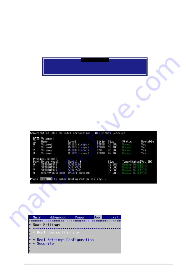
1.  When creating multi-raid via Intel(r) Matrix Storage Manager RAID, we would 

like to assign one array to be the boot drive. The following shows as the 

status of current arrays:

2.  Re-boot the system and press <Del> to enter the Motherboard BIOS Setup 

Utility during POST.

3.  Go to [Boot] menu —> [Boot Device Priority]. Then, select the desired boot 

array and use <+> or <-> key to change the boot device priority.

Содержание TS300-E4

Страница 1: ...TS300 E4 Intel Xeon 3000 Series LGA775 Pedestal 5U Server ...

Страница 2: ...on of business and the like even if ASUS has been advised of the possibility of such damages arising from any defect or error in this manual or product Specifications and information contained in this manual ae furnished for informational use only and are subject to change at any time without notice and should not be construed as a commitment by ASUS ASUS assumes no responsibility or liability for...

Страница 3: ...ormation 1 9 1 6 1 System and HDD LED 1 9 1 6 2 LAN LED 1 10 2 Chapter 2 Hardware setup 2 1 Chassis cover 2 2 2 1 1 Removing the side cover 2 2 2 1 2 Reinstalling the side cover 2 3 2 2 Motherboard overview 2 4 2 3 Central Processing Unit CPU 2 5 2 3 1 Installing the CPU 2 5 2 3 2 Central Processing Unit CPU 2 8 2 4 System memory 2 10 2 4 1 Overview 2 10 2 4 2 Memory configurations 2 10 2 4 3 Inst...

Страница 4: ...0 3 SATA SAS backplane 2 34 2 10 4 Floppy disk drive 2 36 2 10 5 Front I O board 2 38 2 10 6 Chassis footpads and roller wheels 2 40 2 10 7 Power supply unit 2 42 3 Chapter 3 Installation option 3 1 Preparing the system for rack mounting 3 2 4 Chapter 4 Motherboard info 4 1 Motherboard layouts 4 2 4 2 Jumpers 4 6 4 3 Switch 4 11 4 4 Connectors 4 12 4 4 1 Rear panel connectors 4 12 4 4 2 Internal c...

Страница 5: ...rimary Tertiary Fourth IDE Master Slave 5 14 5 3 6 System Information 5 16 5 4 Advanced menu 5 18 5 4 1 CPU Configuration 5 18 5 4 2 MPS Configuration 5 21 5 4 3 Chipset Configuration 5 21 5 4 4 PCI PnP Configuration 5 25 5 4 5 USB Configuration 5 26 5 4 6 ACPI Configuration 5 28 5 4 7 APM Configuration 5 29 5 4 8 Hardware Monitor 5 32 5 5 Server menu 5 34 5 6 Security 5 36 5 7 Boot menu 5 39 5 7 ...

Страница 6: ...1 Creating a RAID 0 set Stripe 6 32 6 3 2 Creating a RAID 1 set Mirror 6 34 6 3 3 Creating a RAID 10 set Stripe Mirror 6 35 6 3 4 Creating a RAID 5 set Parity 6 36 6 3 5 Deleting a RAID set 6 37 6 3 6 Resetting disks to Non RAID 6 38 6 4 Rebuilding the RAID 6 38 6 5 Exiting the Intel Matrix Storage Manager 6 41 6 6 Setting the Boot array use MB BIOS Setup Utility 6 41 6 7 Global Array Manager For ...

Страница 7: ...ver 2003 7 17 7 4 Management applications and utilities installation 7 20 7 4 1 Running the support CD 7 20 7 4 2 Drivers menu 7 20 7 4 3 Management Software menu 7 21 7 4 4 Utilities menu 7 22 7 4 5 Contact information 7 22 Appendix Reference information A 1 450 W single power supply A 2 A 1 1 General description A 2 A 1 2 Specifications A 3 A 2 Simple fixes A 4 ...

Страница 8: ...e harmful interference to radio or television reception which can be determined by turning the equipment off and on the user is encouraged to try to correct the interference by one or more of the following measures Reorient or relocate the receiving antenna Increase the separation between the equipment and receiver Connect the equipment to an outlet on a circuit different from that to which the re...

Страница 9: ...erver carefully read all the manuals included with the server package Before using the server make sure all cables are correctly connected and the power cables are not damaged If any damage is detected contact your dealer as soon as possible To avoid short circuits keep paper clips screws and staples away from connectors slots sockets and circuitry Avoid dust humidity and temperature extremes Plac...

Страница 10: ...ormation This chapter gives information about the motherboard that comes with the server This chapter includes the motherboard layout jumper settings and connector locations 5 Chapter 5 BIOS information This chapter tells how to change system settings through the BIOS Setup menus and describes the BIOS parameters 6 Chapter 6 RAID configuration This chapter provides information on how toconfigure y...

Страница 11: ...n to prevent injury to yourself when trying to complete a task CAUTION Information to prevent damage to the components when trying to complete a task IMPORTANT Instructions that you MUST follow to complete a task NOTE Tips and information to aid in completing a task Conventions To make sure that you perform certain tasks properly take note of the following symbols used throughout this manual ...

Страница 12: ...xii ...

Страница 13: ...1 ASUS TS300 E4 This chapter describes the general features of the barebone server including sections on the front panel and rear panel specifications Chapter 1 Product introduction ...

Страница 14: ...wer supply SATA backplane board SAS backplane board Floppy disk drive 9 cm HDD Blower 12 cm Chassis fan Hot swap HDD trays including HDD screws 4 4 Chassis roller wheels 4 4 Front I O board Cables AC power cable SATA signal cables pre installed SAS signal cables pre installed SMBus cable pre installed System screws and cables System keys 2 pcs Bundled CDs TS300 E4 support CD with ASWM Computer Ass...

Страница 15: ...000 series Intel Core 2 Duo E6000 E4000 Series Intel Pentium 4 Intel Pentium D processor Supports Intel Enhanced Memory 64 Technology EM64T Supports Enhanced Intel SpeedSetp Technology EIST Memory Dual channel memory architecture 4 x 240 pin DIMM sockets support ECC non ECC unbuffered 667 533 MHz DDR2 memory modules Supports 256 MB up to 8 GB of system memory LAN Dual Broadcom BCM5721 Gigabit LAN ...

Страница 16: ...1 x 3 25 inch FDD bay 3 x 5 25 inch drive bays Graphics ATI ES1000 PCI based VGA controller with 32MB DDR display memory Front panel 2 x USB 2 0 ports Rear panel 1 x Serial port COM1 1 x Parallel port 1 x PS 2 keyboard port 1 x PS 2 mouse port 2 x LAN RJ 45 ports 2 x USB 2 0 ports 1 x VGA port Management ASUS Server Web based Management ASWM 2 0 Hardware monitors Voltage temperature CPU and memory...

Страница 17: ...el to access the front panel components The drive bays power and reset buttons LED indicators optical drive floppy drive and USB 2 0 ports are located on the front panel For future installation of 5 25 inch devices two drive bays are available Optical drive Empty 5 25 inch bays Power button Reset button Message LED HDD access LED Power LED Floppy disk drive Security lock Drive bays USB 2 0 ports ...

Страница 18: ...orts expansion slots a chassis lock and intrusion switch a vent for the system fan and power supply module 12 cm system fan Chassis intrusion switch Expansion slots Gigabit LAN1 port Power supply module PS 2 mouse port PS 2 keyboard port USB 2 0 ports Serial port VGA port Parallel port Power connector Gigabit LAN2 port ...

Страница 19: ...e TS300 E4 with the hard disk drive blower installed 1 1 Power supply unit 2 Chassis fan 3 ASUS P5M2 motherboard 4 Chassis intrusion switch 5 Expansion card locks 6 Optical drive 7 2 x 5 25 inch drive bays 8 HDD blower HDD drive cage inside 9 Front I 0 board 10 SATA backplane PA4 4 hot swap SATA configuration 2 3 4 5 6 7 8 9 10 ...

Страница 20: ...2 Chassis fan 3 ASUS P5M2 SAS motherboard 4 Chassis intrusion switch 5 Expansion card locks 6 Optical drive 7 2 x 5 25 inch drive bays 8 HDD blower HDD drive cage inside 9 Front I 0 board 10 SAS backplane PX4 4 hot swap SAS configuration 2 3 4 5 6 7 8 9 10 ...

Страница 21: ...t bezel is closed LED Icon Display status Description System Power LED ON Blinking System power ON System is in suspend mode HDD Access LED OFF Blinking No activity Read write data into the HDD Message LED OFF Blinking System is normal no incoming event ASMS indicates a HW monitor event Hard disk drives Drive Status LED Green Red Green Red Blinking Bridge board connected to backplane Installed HDD...

Страница 22: ...N LED ACT LINK LED SPEED LED Status Description Status Description OFF No link OFF 10 Mbps connection GREEN Linked ORANGE 100 Mbps connection BLINKING Data activity GREEN 1 Gbps connection LAN port LED indications LAN port SPEED LED ACT LINK LED ...

Страница 23: ...ASUS TS300 E4 2 This chapter lists the hardware setup procedures that you have to perform when installing or removing system components Chapter 2 Hardware setup ...

Страница 24: ...lf an inch toward the rear until it is disengaged from the chassis 3 Carefully lift the cover and set it aside Viewing the internal structure Without the side cover the internal structure and installed components of the barebone server vary depending on the model you purchased Refer to section 1 5 Internal features for the different model configurations Perform the procedures in the succeeding sec...

Страница 25: ...r to the corresponding chassis holes and edge 2 Slide the cover toward the front until it snaps in place You may need to remove some of the installed components to access the DIMM sockets and internal connectors Refer to section 2 10 Removable components for instructions 3 Drive in the two screws you removed earlier to secure the side cover 2 3 3 ...

Страница 26: ...assis by nine 9 screws as indicated by the circles in the illustration below Make sure to unplug the power cord before installing or removing any motherboard component or connection Failure to do so can cause you physical injury and damage motherboard components Place this side towards the rear of the chassis Refer to Chapter 4 Motherboard information for detailed information on the motherboard ...

Страница 27: ...he 775 land package Before installing the CPU make sure that the socket box is facing towards you and the load lever is on your left 2 Press the load lever with your thumb A then move it to the left B until it is released from the retention tab Retention tab Load lever This side of the socket box should face you PnP cap A B To prevent damage to the socket pins do not remove the PnP cap unless you ...

Страница 28: ...h your thumb and forefinger to a 100º angle A then push the PnP cap from the load plate window to remove B 5 Position the CPU over the socket making sure that the gold triangle is on the bottom left corner of the socket The socket alignment key should fit into the CPU notch Alignment key Gold triangle mark Load plate A B ...

Страница 29: ...ng the CPU 6 Close the load plate A then push the load lever B until it snaps into the retention tab A B The motherboard supports Intel Xeon 3000 Series LGA775 processors with the Intel Enhanced Memory 64 Technology EM64T Enhanced Intel SpeedStep Technology EIST and Hyper Threading Technology Refer to the Appendix for more information on these CPU features ...

Страница 30: ...um thermal condition and performance When you buy a boxed Intel CPU the package includes the heatsink fan retention brackets screws thermal grease installation manual and other items that are necessary for CPU installation Make sure that you have applied the thermal grease to the top of the CPU before installing the heatsink and fan Refer to the installation manual that came with the CPU package f...

Страница 31: ...2 ASUS TS300 E4 3 Connect the CPU fan cable to the connector on the motherboard Do not forget to connect the CPU fan connector Hardware monitoring errors can occur if you fail to plug this connector ...

Страница 32: ...b site When installing one or two DIMMs install the DIMM s to the blue slots DIMM_A2 DIMM_B2 Three DDR DIMMs intalled into any three memory sockets will function in dual channel asmmetric mode P5M2 P5M2 240 pin DDR2 DIMM Sockets DIMM_A2 DIMM_B1 DIMM_B2 DIMM_A1 112 Pins 128 Pins Recommended memory configurations Mode Single channel Dual channel Dual channel mode interleaved mode asymmetic mode Numb...

Страница 33: ...ning clips snap back in place and the DIMM is properly seated 2 4 4 Removing a DIMM To remove a DIMM 1 Simultaneously press the retaining clips outward to unlock the DIMM 2 Remove the DIMM from the socket A DDR2 DIMM is keyed with a notch so that it fits in only one direction Do not force a DIMM into a socket to avoid damaging the DIMM The DDR2 DIMM sockets do not support DDR DIMMs DO not install ...

Страница 34: ...tached to the chassis through three hooked tabs on the left side and four hinge like tabs on the right side To remove the front panel assembly 1 Locate the four hooked tabs on the chassis side rail 2 Press each lock tab to release the front panel from the chassis 2 5 Front panel assembly 2 5 1 Removing the front panel assembly 3 Pull and swing the left edge of the front panel outward ...

Страница 35: ...o not use too much force when removing the front panel assembly 4 Unhook the hinge like tabs from the holes on the right side of the front panel to completely detach the front panel assembly from the chassis Hinge like tab ...

Страница 36: ...front panel assembly front bezel and front panel cover 1 Insert the four hinge like tabs to the holes on the right edge of the chassis 2 Swing the front panel to the left and fit the four 4 hooked tabs to the left side of the chassis until the tabs snap back in place Hinge like tab 1 1 1 1 2 ...

Страница 37: ...vices If you have previously used and powered up the system and that it may be connected to an AC power source make sure to unplug the power cable before installing or removing any system components Failure to do so may cause damage to the motherboard and other system components To install a 5 25 inch drive 1 Use a Phillips cross screwdriver to turn outward and inward the metal cover of the bay un...

Страница 38: ...ck of the drive 6 Connect a 4 pin plug from the power supply to the power connector on the back of the drive IDE cable Power plug 3 Make sure that the drive and bay hole align as shown When in place the drive protrudes about an inch from the front panel 4 Secure the drive with a screw ...

Страница 39: ... the plastic bay cover opposite the 5 25 inch drive that you installed by pressing the two hooked tabs on each side of the bay cover 8 Reinstall the front panel assembly when done Refer to section 2 5 2 Reinstalling the front panel assembly for instructions ...

Страница 40: ...p drive trays 2 Release a drive tray by pushing the spring lock to the right then pulling the tray lever outward The drive tray ejects slightly after you pull out the lever 3 Firmly hold the tray lever and pull the drive tray out of the bay 4 An empty drive tray requires a metal bracket for support Use a Phillips cross screwdriver to remove the bracket when you are ready to install a hard disk in ...

Страница 41: ...r screws 6 Carefully insert drive tray and push it all the way to the depth of the bay until just a small fraction of the tray edge protrudes 7 Push the tray lever until it clicks and secures the drive tray in place The drive tray is correctly placed when its front edge aligns with the bay edge ...

Страница 42: ...ing an HDD dummy cover The HDD dummy covers come pre installed on the front panel bezel In case you removed the covers follow these steps to re install them To install an HDD dummy cover 1 From the inside of the front panel assembly insert the flat end of a dummy cover into the slot as shown The end with the hook tab should be close to the front panel LEDs Flat end Hook tab ...

Страница 43: ...etal bracket to the chassis Set aside the metal bracket for future use 3 Align the card golden fingers to the slot and its metal bracket to the slot opening on the chassis 4 Press the card firmly until it is properly seated on the slot 5 Secure the card to the chassis with the bracket screw you removed earlier Make sure to unplug the power cord before installing or removing expansion cards Failure...

Страница 44: ...g an expansion card To remove an expansion card 1 Remove the screw that secures the card to the chassis 2 Carefully remove the card from the slot 3 Reinstall the metal bracket and secure it to the chassis with the screw that you removed earlier ...

Страница 45: ...1 SATA1 SATA2 SATA3 SATA4 ICS 954123BFLF 30 5cm 12in Mini SAS2 Mini SAS2 6 8 7 5 1 2 3 4 9 10 11 2 9 Cable connections The bundled system cables are pre connected before shipment You do not need to disconnect these cables unless you will remove pre installed components to install additional devices Refer to Chapter 4 for detailed information on the connectors Standard cables connected to the mothe...

Страница 46: ...status See section 1 6 LED information for details Front side The front side of the SATA backplane faces the front panel when installed This side includes four SATA connectors for the hot swap drive trays Drive status LEDs SATA Port0 CON1 SATA Port1 CON3 SATA Port2 CON5 SATA Port3 CON7 Each SATA connector is labeled CON1 CON3 CON5 CON7 so you can easily determine their counterpart connectors at th...

Страница 47: ...7R Upper 6 1 pins J1 SMBus connector connects the SMB cable from the BPSMB1 connector on the motherboard CON2 CON4 CON6 CON8 PSUSMB1 24 5cm 9 6in 21 8cm 8 6in Intel MCH Mukilteo 2 Intel ICH7R ASMB3 LGA775ll LGA775 Intel PXH V ATXPWR1 ATX12V1 KBPWR1 USBPW12 CPU_FAN2 FRNT_FAN1 FRNT_FAN2 CPU_FAN1 REAR_FAN2 REAR_FAN1 PS 2KBMS T Mouse B Keyboard USB12 PARALLEL PORT VGA1 COM1 LAN1 LAN2 DDR2 DIMM_A1 64 b...

Страница 48: ...define your desired SATA configuration The picture below shows the location of jumper J3 with pins 1 3 and 2 4 shorted Refer to the table for the jumper settings and the appropriate ID for each SATA HDD bay J3 setting 1 3 shorted 2 4 shorted Device SATA ID Drive Bay 1 ID0 Drive Bay 2 ID1 Drive Bay 3 ID2 Drive Bay 4 ID3 ...

Страница 49: ...backplane connect to the front panel LEDs to indicate HDD access HDD failure thermal failure or fan failure See section 1 6 LED information Front side The front side of the SAS backplane faces the front panel when installed This side includes four SAS connectors for the hot swap drive trays HDD status LEDs HDD activity LEDs Disk drive 1 Disk drive 2 Disk drive 3 Disk drive 4 Front Side Connector S...

Страница 50: ...r connectors SAS interfaces for the motherboard SAS connector or the SAS control card an HDD fan connector and SMBus connectors Upper 6 1 pin J2 SMBus connector connects the SMB cable from the motherboard Fan connector for HDD fan SAS connector connect to the Min SAS1 connector Select Address as default Select Address You do not have to change these jumpers Please keep the jumpers as default ...

Страница 51: ...ou need to replace defective components This section tells how to remove the following components 2 Locate the four screws that secure the fan to the chassis 3 Remove the four screws while carefully supporting the chassis fan with your free hand to prevent it from falling off Set the screws aside 4 Carefully remove the chassis fan 1 Chassis fan 2 HDD blowers 3 SATA SAS backplanes 4 Floppy disk dri...

Страница 52: ...ive in the four screws you removed earlier to secure the fan to the chassis 5 Remove the four screws that secure the metal shroud to the fan Set the screws aside To reinstall the chassis fan 1 Drive in the four screws you removed earlier into the fan screw holes to secure the metal shroud to the fan ...

Страница 53: ...e 3 pin fan cable from the fan connector on the backplane 4 Firmly grip the blower case as shown then slide it out of the chassis in the direction of the arrow until the tabs are released from the holes of the HDD cage 3 Loosen the thumb screw that secures the HDD blower case to the chassis 4 Plug the chassis fan cable to the connector Rear_FAN1 on the motherboard ...

Страница 54: ...ower from the case To reinstall the HDD blower 1 Replace the blower into the case 2 Secure the blower to the case with the two screws you removed earlier 5 Remove the two screws on the blower case using a Phillips screwdriver Set the screws aside ...

Страница 55: ...4 4 Drive in the thumb screw to secure the HDD blower case 5 Connect the 3 pin fan cable to the fan connector on the backplane 3 Slide in the blower case as shown making sure the tabs fit into the holes on the HDD cage ...

Страница 56: ...ct all cables from the SATA SAS backplane When disconnecting a cable hold and firmly pull the cable plug DO NOT pull the cable itself Doing so may damage the cable 4 From the inner edge push the backplane outward so that the outer edge protrudes slightly from the slot 5 From the outer edge firmly hold the backplane and carefully slide it out 3 Remove the 2 screws on the backplane ...

Страница 57: ...l like dents on the slot to ensure that it fits securely 3 Slide the backplane into the slot until it fits If correctly installed the outer edge of the backplane aligns with the corner of the drive cage 4 Fasten the 2 screws on the backplane 5 Connect the appropriate cables to the backplane Refer to sections 2 9 2 SATA backplane connections and 2 9 3 SAS backplane connections for details Rail like...

Страница 58: ...e To remove the floppy disk drive 1 Remove the screw that secures the drive to the chassis You need to remove the front panel assembly before you can remove the floppy disk drive Refer to section 2 5 1 Removing the front panel assembly for instructions 3 Disconnect the floppy disk cable and power cable from the drive to completely release the drive ...

Страница 59: ...on on the left side close to the HDDs 2 Connect the drive signal cable and power cable 4 Secure the drive cage with a screw 3 Carefully push the drive into the bay until the drive cage fits the front edge of the bay Floppy drive power cable Floppy drive signal cable Red stripe to match Pin 1 on the connector ...

Страница 60: ...2 5 1 Removing the front panel assembly for instructions To remove the front I O board 1 Remove the screw that secures the front I O board bracket to the front panel 4 Remove the screw that secures the I O board to the bracket 2 Carefully pull out the bracket until you see the cables connected to the I O board 3 Disconnect all the cables from the I O board ...

Страница 61: ...o the bracket with a screw 2 Position the I O board into the bay with the component side to the left close to the HDDs Connect the I O cables to the connectors on the back of the I O board 3 Insert the I O board into the bay until the bracket fits the front edge of the bay 4 Secure the I O board bracket with a screw USB 2 0 connector ...

Страница 62: ...place the footpads with the bundled roller wheels you wish to install the system to a rack Refer to Chapter 3 Installation options of this user guide and to the Rackmount Kit user guide for instructions To remove the footpads 1 Lay the system chassis on its side 2 Use a flat screwdriver to flip out the top layer of a footpad 4 Repeat steps 2 and 3 to remove the other three footpads 3 Remove the fo...

Страница 63: ...unt the system to a rack For convenient transport install the roller wheels the came with the system package Each wheel has a brake lock to stabilize the chassis in place To install the chassis wheels 1 Lay the chassis in its side 2 Locate the designated screw holes for each of the four wheel sets Take note of the numbers alongside each hole when placing screws 3 Secure each wheel to the bottom of...

Страница 64: ...t for the power supply specifications 2 1 3 2 1 3 Model PA4 1 24 pin ATX motherboard power connector 2 4 pin 12V motherboard power connector hidden behind the cables 3 4 pin plug optical drive 4 2 x 4 pin plugs SATA backplane 5 4 pin plug floppy disk drive hidden behind the backplane Model PX4 1 24 pin ATX motherboard power connector 2 4 pin 12V motherboard power connector hidden behind the cables...

Страница 65: ...panel assembly Refer to section 2 5 1 Removing the front panel assembly 3 Lay the chassis on a flat stable surface 4 Locate the four screws on the rear panel Remove the screws and set them aside 5 Locate and remove the screws that secure the PSU bracket to the chassis 6 Slide the bracket in the direction of the arrow and remove it from the chassis ...

Страница 66: ...slide the PSU in the direction of the arrow until it disengages from the chassis To reinstall the power supply unit 1 Carefully slide the PSU in the direction of the arrow 2 Secure the PSU to the chassis with the four screws you removed earlier ...

Страница 67: ...2 45 ASUS TS300 E4 3 Slide in the PSU bracket 4 Align the screw holes 5 Secure the bracket with screws you removed earlier ...

Страница 68: ...Chapter 2 Hardware setup 2 46 ...

Страница 69: ...3 ASUS TS300 E4 Chapter 3 Installation option This chapter describes how to install optional components into the barebone server ...

Страница 70: ...h the Rackmount Rail Kit for instructions on how to attach the rails and on the barebone server system and the corresponding rails on the industrial rack 4 Locate two round mylars on top cover 5 Carefully remove each mylar using a sharp flat object such as the edge of a cutter Removing the top cover To remove the top cover 1 Remove the chassis cover Refer to section 2 1 1 Removing the side cover 2...

Страница 71: ...SUS TS300 E4 This chapter gives information about the motherboard that comes with the server This chapter includes the motherboard layout jumper settings and connector locations Chapter 4 Motherboard info ...

Страница 72: ..._A1 64 bit 240 pin module DDR2 DIMM_B1 64 bit 240 pin module DDR2 DIMM_A2 64 bit 240 pin module DDR2 DIMM_B2 64 bit 240 pin module P5M2 PCIE1 PCIX3 DIP_SW1 PCI4 PCIX2 CR2032 3V Lithium Cell CMOS Power SB_PWR1 SuperI O 8Mbit Flash BIOS Broadcom BCM5721 Broadcom BCM5721 LAN_EN1 VGA_EN1 RECOVERY1 CLRTC1 RAID_SEL1 LAN_EN2 ATI ES1000 LSI1068 P5M2 SAS VGA Controller SAS_EN1 DDRV1 TPM1 COM2 BUZZ1 BPSMB1 ...

Страница 73: ...DR2 DIMM_A1 64 bit 240 pin module DDR2 DIMM_B1 64 bit 240 pin module DDR2 DIMM_A2 64 bit 240 pin module DDR2 DIMM_B2 64 bit 240 pin module P5M2 PCIE1 PCIX3 DIP_SW1 PCI4 PCIX2 CR2032 3V Lithium Cell CMOS Power SB_PWR1 SuperI O 8Mbit Flash BIOS Broadcom BCM5721 Broadcom BCM5721 LAN_EN1 VGA_EN1 RECOVERY1 CLRTC1 LAN_EN2 ATI ES1000 VGA Controller DDRV1 TPM1 COM2 BUZZ1 BPSMB1 RAID_EN1 USBPW34 USB34 FLOP...

Страница 74: ...45 port 4 12 Slots Sockets Page 1 CPU socket 2 5 2 DDR2 DIMM slots 2 10 Jumpers Page 1 Clear RTC RAM CLRTC1 4 6 2 USB device wake up 3 pin USBPW12 USBPW34 4 7 3 Keyboard Mouse power 3 pin KBPWR1 4 8 4 VGA controller setting 3 pin VGA_EN1 4 8 5 Gigabit LAN controller setting 3 pin LAN_EN1 LAN_EN2 4 9 6 RAID controller selection 3 pin RAID_SEL1 4 9 7 SAS controller setting 3 pin SAS_EN1 4 10 8 Force...

Страница 75: ...0 1 pin USB34 4 15 6 Serial port connector 10 1 pin COM2 4 16 7 SAS LSI1068 ports LED connector 18 1 pin SASLED1 4 16 8 Mini SAS connectors 4 17 9 CPU and system fan connectors 4 pin CPU_FAN1 2 4 18 REAR_FAN1 2 FRNT_FAN1 2 10 Backplane SMBus connector 6 1 pin BPSMB1 4 18 11 Power supply SMBus connector 5 pin PSUSMB1 4 19 12 ATX power connectors 24 pin ATXPWR1 4 pin ATX12V2 4 19 13 Auxiliary panel ...

Страница 76: ...meters by erasing the CMOS RTC RAM data The onboard button cell battery powers the RAM data in CMOS which include system setup information such as system passwords To erase the RTC RAM 1 Turn OFF the computer and unplug the power cord 2 Remove the onboard battery 3 Move the jumper cap from pins 1 2 default to pins 2 3 Keep the cap on pins 2 3 for about 5 10 seconds then move the cap back to pins 1...

Страница 77: ...supply in reduced power mode The USB device wake up feature requires a power supply that can provide 500mA on the 5VSB lead for each USB port otherwise the system would not power up If you are using Windows 2000 you need to install Service Pack 4 to wake up the system from S4 sleep mode The total current consumed must NOT exceed the power supply capability 5VSB whether under normal condition or in...

Страница 78: ... is the Space Bar or click the mouse This feature requires an ATX power supply that can supply at least 1A on the 5VSB lead and a corresponding setting in the BIOS 4 VGA controller setting 3 pin VGA_EN1 These jumpers allow you to enable or disable the onboard ATI RAGE XL PCI VGA controller Set to pins 1 2 to activate the VGA feature P5M2 P5M2 Keyboard Power Setting KBPWR1 Default 5V 5VSB 2 3 1 2 P...

Страница 79: ...umper allows you to select the RAID configuration utility to use when you create disk arrays Place the jumper caps over pins 1 2 if you want to use the LSI Logic Embedded SATA RAID Setup Utility default otherwise place the jumper caps to pins 2 3 to use the Intel Matrix Storage Manager P5M2 P5M2 LAN_EN1 Setting Enable Default Disable LAN_EN1 2 1 2 3 P5M2 P5M2 LAN_EN2 Setting Enable Default Disable...

Страница 80: ...d xxxx xxx ROM and the AFUDOS EXE utility 4 Insert the floppy disk then turn on the system to update the BIOS 5 Shut down the system 6 Set the jumper back to pins 1 2 7 Turn on the system and hold down the Del key during the boot process then enter BIOS setup to re enter data 7 SAS controller setting 3 pin SAS_EN1 PX4 model only This jumper allows you to enable or disable the onboard LSI SAS1068 c...

Страница 81: ...N4 ON 7 REAR_FAN1 OFF 8 REAR_FAN2 ON If you use a 4 pin fan but set the DIP switch for a 3 pin fan the fan you installed may not work If you use a 3 pin fan but set the DIP switch for a 4 pin fan the fan controll will not work and the fan you installed will always run at full speed P5M2 DIP switches DIP_SW1 ON 4 PIN FAN OFF 3 PIN FAN SW1_CPU_FAN1 SW2_CPU_FAN2 SW3_FRNT_FAN1 SW4_FRNT_FAN2 SW5_FRNT_F...

Страница 82: ...S 2 keyboard port purple This port is for a PS 2 keyboard 4 USB 2 0 ports 1 and 2 These two 4 pin Universal Serial Bus USB ports are available for connecting USB 2 0 devices 5 Serial COM1 port This 9 pin communication port is for pointing devices or other serial devices 6 VGA port This port is for a VGA monitor or other VGA compatible devices 7 Gigabit LAN1 RJ 45 port This ports allow Gigabit conn...

Страница 83: ... 34 1 pin FLOPPY1 This connector is for the provided floppy disk drive FDD signal cable Insert one end of the cable to this connector then connect the other end to the signal connector at the back of the floppy disk drive Pin 5 on the connector is removed to prevent incorrect cable connection when using a FDD cable with a covered Pin 5 Pin 20 on the IDE connector is removed to match the covered ho...

Страница 84: ...ICH7R Southbridge These connectors are set IDE mode by default In IDE mode you can connect Serial ATA boot data hard disk drives to these connectors If you intend to create a Serial ATA RAID set using these connectors set the Configure SATA as item in the BIOS to RAID See section 5 3 4 IDE Configuration for details Serial ATA hard disk drive connection Connector Setting Use SATA1 SATA2 Master Boot...

Страница 85: ...nel connector 5 USB connector 10 1 pin USB34 This connector is for USB 2 0 ports Connect the USB module cable to this connector then install the module to a slot opening at the back of the system chassis This USB connector complies with USB 2 0 specification that supports up to 480 Mbps connection speed P5M2 P5M2 SCSI SATACard Activity LED Connector HDLED1 1 ADD_IN_CARD_ACT ADD_IN_CARD_ACT NC NC P...

Страница 86: ...D connector 18 1 pin SASLED1 For PX4 model only This connector is for SAS link state s LED The active LOW Fault LED signals are nominally configured to indicate a SAS link fault for each respective phy The active LOW Activity LED signals are nominally configured to indicate SAS link activity P5M2 P5M2 COM Port Connector PIN 1 COM2 P5M2 P5M2 SASLED Connector SASLED1 ACT_LED0 ACT_LED1 ACT_LED2 ACT_L...

Страница 87: ...nd Serial ATA Each connector supports up to four 4 devices To connect the mini SAS cable Plug in the mini SAS cable to the mini SAS connector until the cable lock snaps in place To disconnect the mini SAS cable 1 With your thumb push down the cable lock to release 2 While still keeping your thumb s grip on the cable lock carefully pull away the cable from the connector 1 2 P5M2 P5M2 SAS MINI SAS c...

Страница 88: ...mponents These are not jumpers Do not place jumper caps on the fan connectors 10 Backplane SMBus connector 6 1 pin BPSMB1 This connector allows you to connect SMBus System Management Bus devices Devices communicate with an SMBus host and or other SMBus devices using the SMBus interface P5M2 P5M2 Fan Connectors GND FANPWR1 FANOUT4 CPU_FAN1 GND FANPWR4 FANOUT4 FRNT_FAN2 FRNT_FAN1 GND FANPWR3 FANOUT4...

Страница 89: ...rientation Find the proper orientation and push down firmly until the connectors completely fit Do not forget to connect the 4 pin ATX 12 V power plug otherwise the system will not boot up P5M2 P5M2 Power Supply SMBus Connector PSUSMB1 3 3V Remote Sense GND NC PSU_I2CDATA PSU_I2CCLK P5M2 P5M2 ATX Power Connector 3 Volts 3 Volts Ground 5 Volts 5 Volts Ground Ground Power OK 5V Standby 12 Volts 5 Vo...

Страница 90: ... external detection mechanism such as a chassis intrusion sensor or microswitch When you remove any chassis component the sensor triggers and sends a high level signal to this lead to record a chassis intrusion event If you like to disable this feature please place one jumper cap over the CASEOPEN and GND leads 4 Locator LED 2 pin LOCATORLED1 and 2 pin LOCATORLED2 Both of the 2 pin connector is fo...

Страница 91: ...when the system is in the boot process until the operating system is loaded Hard disk drive activity LED Red 2 pin HD_LED This 2 pin connector is for the HDD Activity LED Connect the HDD Activity LED cable to this connector The IDE LED lights up or flashes when data is read from or written to the HDD System warning speaker Orange 4 pin SPKEROUT This 4 pin connector is for the chassis mounted syste...

Страница 92: ...Chapter 4 Motherboard information 4 22 ...

Страница 93: ...3 ASUS TS300 E4 This chapter tells how to change system settings through the BIOS Setup menus and describes the BIOS parameters Chapter 5 BIOS information ...

Страница 94: ...otable floppy disk DOS environment a Insert a 1 44MB floppy disk into the drive b At the DOS prompt type format A S then press Enter Windows XP environment a Insert a 1 44 MB floppy disk to the floppy disk drive b Click Start from the Windows desktop then select My Computer c Select the 3 1 2 Floppy Drive icon d Click File from the menu then select Format A Format 3 1 2 Floppy Disk window appears ...

Страница 95: ...e Update Utility Version 1 19 ASUS V2 07 03 11 24BB Copyright C 2002 American Megatrends Inc All rights reserved Reading flash done Write to file ok A Main filename Extension name 1 Copy the AFUDOS utility afudos exe from the motherboard support CD to the bootable floppy disk you created earlier 2 Boot the system in DOS mode then at the prompt type afudos o filename where the filename is any user ...

Страница 96: ...oad the latest BIOS file for the motherboard Save the BIOS file to a bootable floppy disk A afudos iP5MT rom Write the BIOS filename on a piece of paper You need to type the exact BIOS filename at the DOS prompt 4 The utility verifies the file and starts updating the BIOS Do not shut down or reset the system while updating the BIOS to prevent system boot failure A afudos iI8043A0 rom AMI Firmware ...

Страница 97: ...eboot the system from the hard disk drive A afudos iI8043A0 ROM AMI Firmware Update Utility Copyright C 2004 American Megatrends Inc All Rights Reserved Ver 4 04 ASUSTEK Ver 3 12 Bootblock chechsum OK Module checksums OK Erasing flash done Writing flash done Verifying flash done Program ended normally ...

Страница 98: ... disk for the original or updated BIOS file 4 Restart the system after the utility completes the updating process When found the utility reads the BIOS file and starts flashing the corrupted BIOS file DO NOT shut down or reset the system while updating the BIOS Doing so can cause system boot failure Prepare the motherboard support CD or the floppy disk containing the updated motherboard BIOS befor...

Страница 99: ...hecksum Starting BIOS recovery Checking for floppy Floppy not found Checking for CD ROM CD ROM found Reading file I8043A0 rom Completed Start flashing When no floppy disk is found the utility automatically checks the optical drive for the original or updated BIOS file The utility then updates the corrupted BIOS file Bad BIOS checksum Starting BIOS recovery Checking for floppy DO NOT shut down or r...

Страница 100: ... the BIOS from an updated BIOS file View the BIOS version information This utility is available in the support CD that comes with the motherboard package Quit all Microsoft Windows applications before you update the BIOS using this utility Updating the BIOS through a BIOS file To update the BIOS through a BIOS file 1 Launch the ASUS Update utility from the Windows desktop by clicking Start Program...

Страница 101: ...ress Del during the Power On Self Test POST to enter the Setup utility otherwise POST continues with its test routines If you wish to enter Setup after POST restart the system by pressing Ctrl Alt Delete or by pressing the reset button on the system chassis You can also restart by turning the system off and then back on Do this last option only if the first two failed The Setup program is designed...

Страница 102: ...n keys At the bottom right corner of a menu screen are the navigation keys for that particular menu Use the navigation keys to select items in the menu and change the settings 5 2 1 BIOS menu screen Some of the navigation keys differ from one screen to another Navigation keys Sub menu items System Date Sun 01 01 2006 System Time 11 10 19 Legacy Diskette A 1 44M 3 5 in IDE Configuration System Info...

Страница 103: ...ht side of a menu screen when there are items that do not fit on the screen Press the Up Down arrow keys or Page Up Page Down keys to display the other items on the screen 5 2 9 General help At the top right corner of the menu screen is a brief description of the selected item Main menu items System Date Mon 05 30 2005 System Time 11 10 19 Legacy Diskette A 1 44M 3 5 in IDE Configuration System In...

Страница 104: ...s Disabled 360K 5 25 in 1 2M 5 25 in 720K 3 5 in 1 44M 3 5 in 2 88M 3 5 in Refer to section 5 2 1 BIOS menu screen for information on the menu screen items and how to navigate through them v02 58 C Copyright 1985 2004 American Megatrends Inc System Date Sun 01 01 2006 System Time 11 10 19 Legacy Diskette A 1 44M 3 5 in IDE Configuration System Information Select Screen Select Item Change field Tab...

Страница 105: ...t Item Change Field Tab Select field F1 General Help F10 Save and Exit ESC Exit BIOS SETUP UTILITY Main v02 58 C Copyright 1985 2004 American Megatrends Inc Configure SATA as IDE Sets the configuration for the Serial ATA connectors supported by the Southbridge chip Configuration options IDE RAID AHCI If you want to use the Serial ATA hard disk drives as Parallel ATA physical storage devices set th...

Страница 106: ...32122A Size 2 1GB LBA Mode Supported Block Mode 16 Sectors PIO Mode Supported Async DMA MultiWord DMA 2 Ultra DMA Ultra DMA 5 SMART Monitoring Supported Type Auto LBA Large Mode Auto Block Multi sector Transfer M Auto PIO Mode Auto DMA Mode Auto SMART Monitoring Auto 32Bit Data Transfer Enabled Select the type of device connected to the system The item Legacy IDE Channels appears only when you set...

Страница 107: ...mode if the device supports this mode and if the device was not previously formatted with LBA mode disabled Configuration options Disabled Auto Block Multi sector Transfer Auto Enables or disables data multi sectors transfers When set to Auto the data transfer from and to the device occurs multiple sectors at a time if the device supports multi sector transfer feature When set to Disabled the data...

Страница 108: ... Date 09 04 2006 Processor Information System Memory Information Select Screen Select Item Change Option Tab Select field F1 General Help F10 Save and Exit ESC Exit BIOS SETUP UTILITY Main Processor Information CPU1 Band Genuine Intel R CPU 3 80GHz ID uCode 06F4h 026h Speed 3 80GHz Ratio Actual 19 Max 19 Cache L1 16KB L2 2038KB Select Screen Select Item Change Option Tab Select field F1 General He...

Страница 109: ...7 Total Memory 1024MB DIMM_A1 None DIMM_A2 1024MB DIMM_B1 None DIMM_B2 None Select Screen Select Item Change Option Tab Select field F1 General Help F10 Save and Exit ESC Exit BIOS SETUP UTILITY Main System Memory Displays the auto detected total system memory ...

Страница 110: ...is menu show the CPU related information that the BIOS automatically detects Select Screen Select Item Change Option F1 General Help F10 Save and Exit ESC Exit Disabled for WindowsXP BIOS SETUP UTILITY Advanced Configure Advanced CPU settings Module Version 3D 05 Manufacturer Intel Brand String Genuine Intel R CPU 3 80GHz Frequency 3 80 GHz FSB Speed 800 MHz Cache L1 16 KB Cache L2 1024 KB Ratio A...

Страница 111: ...with a BIOS file that supports EIST Execute Disable Bit Enabled When set to Disabled the XD feature flag returns to 0 Configuration options Disabled Enabled Single Logical Processor Mode Disabled Allows you to enable or disable the single logical processor mode Configuration options Disabled Enabled The following item appears only when you installed an Intel Pentium D series processor The followin...

Страница 112: ...ars only when the CPU installed supports the C State technology Intel C state tech C1 Config Enhanced When set to Standard it runs in the conventional C State When set to Enhanced it runs in the enhanced C State Configuration options Standard Enhanced ...

Страница 113: ...OM in the onboard LAN controller Configuration options Disabled Enabled 5 4 3 Chipset Configuration The Chipset Configuration menu allows you to change the advanced chipset settings Select an item then press Enter to display the sub menu Select Screen Select Item Change Option F1 General Help F10 Save and Exit ESC Exit v02 58 C Copyright 1985 2004 American Megatrends Inc BIOS SETUP UTILITY Advance...

Страница 114: ...on options Disabled Enabled DRAM Frequency Auto When Configure DRAM Timing by SPD is enabled you are not allowed change the setting of this item The motherboard automatically sets the DDR operating frequency according to the DRAM SPD When Configure DRAM Timing by SPD is disabled this items allows you to set the DDR operating frequency manually Configuration options Auto 533 MHz 667 MHz Configure D...

Страница 115: ... DRAM Clocks 4 DRAM Clocks 5 DRAM Clocks 6 DRAM Clocks DRAM RAS Precharge 6 DRAM Clocks Controls the idle clocks after issuing a precharge command to the DDR SDRAM Configuration options 2 DRAM Clocks 3 DRAM Clocks 4 DRAM Clocks 5 DRAM Clocks 6 DRAM Clocks DRAM RAS Activate to Precharge Delay 15 DRAM Clocks Configuration options 4 DRAM Clocks 5 DRAM Clocks 15 DRAM Clocks Boot Graphic Adapter Priori...

Страница 116: ...lect Screen Select Item Change Option F1 General Help F10 Save and Exit ESC Exit v02 58 C Copyright 1985 2004 American Megatrends Inc BIOS SETUP UTILITY Advanced S e l e c t t h e d e c o d e range for IO Configure advanced settings for PCI X Hub I O Port Decode 4K Decode VGA 16 Bit Decode Enabled I O Port Decode 4K Decode Allows you to set the decode range for the I O controller Configuration opt...

Страница 117: ...t to No BIOS configures all the devices in the system When set to Yes and if you install a Plug and Play operating system the operating system configures the Plug and Play devices not required for boot Configuration options No Yes Palette Snooping Disabled When set to Enabled the pallete snooping feature informs the PCI devices that an ISA graphics device is installed in the system so that the lat...

Страница 118: ... or Full Speed 12 Mbps Configuration options HiSpeed Full Speed BIOS EHCI Hand Off Enabled Allows you to enable or disable the BIOS EHCI hand off support Configuration options Disabled Enabled 5 4 5 USB Configuration The items in this menu allows you to change the USB related features Select an item then press Enter to display the configuration options Select Screen Select Item Change Option F1 Ge...

Страница 119: ... If set to Auto the part of less than 530MB of USB devices is emulated as floppy disk and the rest part is emulated as hard disk Configuration options Auto Floppy Forced FDD Hard Disk CDROM Select Screen Select Item Change Option F1 General Help F10 Save and Exit ESC Exit v02 58 C Copyright 1985 2004 American Megatrends Inc BIOS SETUP UTILITY Advanced Select the decode range for IO USB Mass Storag...

Страница 120: ...dless Mode Disabled Allows you to enable or disable the Headless operation mode through ACPI Disabled Enabled ACPI EMS Support Disabled Allows you to enable or disable ACPI EMS support Disabled Enabled ACPI MCFG Support Enabled Allows you to enable or disable ACPI MCFG support Disabled Enabled Select Screen Select Item Change Option F1 General Help F10 Save and Exit ESC Exit v02 58 C Copyright 198...

Страница 121: ...ect the duty cycle in the throttle mode Configuration options 87 5 75 0 62 5 50 37 5 25 12 5 Power Button Function On Off Allows you to select the power button function Configuration options On Off Suspend Power Management APM Enabled Allows you to enable or disable the APM Configuration options Disabled Enabled Select Screen Select Item Change Option F1 General Help F10 Save and Exit ESC Exit v02...

Страница 122: ...auses an initialization string that turns the system power on Resume On LAN Disabled When set to Enabled this parameter allows you to turn on the system through a PCI LAN or modem card This feature requires an ATX power supply that provides at least 1A on the 5VSB lead Configuration options Disabled Enabled Resume By PME Disabled When set to Enabled this parameter allows you to turn on the system ...

Страница 123: ...arm Second appear with set values Configuration options Disabled Enabled The following items appear only when the Resume On By RTC Alarm item is set to Enabled RTC Alarm Date Days 15 To set the alarm date highlight this item and press the or key to make the selection Configuration options Everyday 1 2 3 31 System Time 12 30 30 To set the alarm time highlight this item and press the or key to make ...

Страница 124: ...ration Configuration options Disabled Enabled When the Intel Pentium 4 and Pentium D Series CPU CPU1 Temperature item appears showing the CPU temperature currently detected when the Intel Core 2 Due Series CPU is installed CPU1 Throttle Temp Margin appears Hardware Monitor CPU1 Throttle Temp Margin 49ºC 120ºF System1 Temperature 42ºC 107 5ºF System2 Temperature 46ºC 114 5ºF CPU Fan1 Speed 3884RPM ...

Страница 125: ... VTT Voltage 3V Voltage 5V Voltage 5VSB Voltage VBAT Voltage The onboard hardware monitor automatically detects the voltage outputs through the onboard voltage regulators When the Intel Pentium 4 and Pentium D Series CPU CPU1 Temperature item appears showing the CPU temperature currently detected when the Intel Core 2 Due Series CPU is installed Offset To CPU1 TControl item appears ...

Страница 126: ... BIOS POST Always Terminal Type ANSI VT UTFB Combo Key Support Disabled The following items appear only when the Remote Access item is set to Enabled 5 5 Server menu The Server menu items allow you to customize the server features Select Screen Select Item Change Option F1 General Help F10 Save and Exit ESC Exit v02 58 C Copyright 1985 2004 American Megatrends Inc BIOS SETUP UTILITY Main Advanced ...

Страница 127: ... Configuration options None Hardware Software Redirection After BIOS POST Always Sets the redirection mode after the BIOS Power On Self Test POST Some operating systems may not work when this item is set to Always Configuration options Disabled Boot Loader Always Terminal Type ANSI Allows you to select the target terminal type Configuration options ANSI VT100 VT UTF8 VT UTF8 Combo Key Support Disa...

Страница 128: ...of the screen shows the default Not Installed After you set a password this item shows Installed To set a Supervisor Password 1 Select the Change Supervisor Password item then press Enter 2 From the password box type a password composed of at least six letters and or numbers then press Enter 3 Confirm the password when prompted The message Password Installed appears after you successfully set your...

Страница 129: ...s not allow change to any field Limited allows changes only to selected fields such as Date and Time Full Access allows viewing and changing all the fields in the Setup utility Change User Password Select this item to set or change the user password The User Password item on top of the screen shows the default Not Installed After you set a password this item shows Installed To set a User Password ...

Страница 130: ...rd Lock Mode Enabled When set to Enabled the keyboard is locked and the user has no privilege to launch the BIOS setup utility when installing adapter cards during option ROM initialization Configuration options Disabled Enabled Removable Device Boot Enabled Allows you to enable or disable booting from a legacy floppy USB floppy or IDE optical drive Configuration options Disabled Enabled Flash Wri...

Страница 131: ...er Security Boot Exit 5 7 1 Boot Device Priority Select Screen Select Item Change Option F1 General Help F10 Save and Exit ESC Exit v02 58 C Copyright 1985 2004 American Megatrends Inc BIOS SETUP UTILITY Boot Specifies the boot sequence from the available devices A device enclosed in parenthesis has been disabled in the corresponding menu Boot Device Priority 1st Boot Device 1st FLOPPY DRIVE 2nd B...

Страница 132: ... POST items Configuration options Disabled Enabled Full Logo Display Enabled Allows you to enable or disable the full screen logo display feature Configuration options Disabled Enabled Set this item to Enabled to use the ASUS MyLogo2 feature Bootup Num Lock On Allows you to select the power on state for the NumLock Configuration options Off On PS 2 Mouse Support Auto Allows you to enable or disabl...

Страница 133: ...t this option then press Enter or simply press F10 to save your changes to CMOS before exiting the Setup utility When a confirmation window appears select OK then press Enter to save your changes and exit Setup If you wish to cancel the command select Cancel then press Enter to return to the Exit menu Exit Discard Changes Select this option then press Enter to exit the Setup utility without saving...

Страница 134: ...n then press Enter to load the optimized settings for each of the Setup menu items When a confirmation window appears select OK then press Enter to load the default settings If you wish to cancel the command select Cancel then press Enter to return to the Exit menu ...

Страница 135: ...3 ASUS TS300 E4 This chapter provides information on how toconfigure your hard disk drives as RAID sets Chapter 6 RAID Configuration ...

Страница 136: ...e entire system Use two new drives or use an existing drive and a new drive for this setup The new drive must be of the same size or larger than the existing drive RAID 1 E Enhanced RAID 1 has a striped layout with each stripe unit having a secondary or alternate copy stored on a different disk You can use three or more hard disk drives for this configuration RAID 10 0 1 is data striping and data ...

Страница 137: ...his 1 Enter the BIOS Setup during POST 2 Go to the Main Menu select IDE Configuration then press Enter 3 Set the ATA IDE Configuration item to Enhanced Mode then press Enter 4 Set the Configure SATA As item to RAID 5 Save your changes then exit the BIOS Setup 6 1 4 RAID configuration utility Depending on the RAID_SEL1 jumper setting and the operating system you can select a utility to create a RAI...

Страница 138: ...edded SATA RAID Setup Utility For PA4 model only The LSI Logic Embedded SATA RAID Setup Utility allows you to create RAID 0 and RAID 1 set s from SATA hard disk drives supported by the motherboard ICH7R Southbridge chip To enter the LSI Logic Embedded SATA RAID Setup Utility 1 Turn on the system after installing all the SATA hard disk drives 2 During POST the LSI Logic Embedded SATA RAID Setup Uti...

Страница 139: ...data consistency of the logical drives of a created RAID set 6 2 1 Creating a RAID 0 or RAID 1 set The LSI Logic Embedded SATA RAID Setup Utility allows you to create a RAID 0 or RAID 1 set using two types of configurations Easy and New In Easy Configuration the logical drive parameters are set automatically including the size and stripe size RAID 1 only In New Configuration you manually set the l...

Страница 140: ...SELECTION MENU displays the available drives connected to the SATA ports Select the drives you want to include in the RAID set then press SpaceBar When selected the drive indicator changes from READY to ONLIN A X Y where X is the array number and Y is the drive number The information of the selected hard disk drive displays at the bottom of the screen ...

Страница 141: ...00 E4 6 5 Press F10 select the configurable array then press SpaceBar Press F10 again the logical drive information appears including a Logical Drive menu that allows you to change the logical drive parameters ...

Страница 142: ...ating a RAID 1 set 8 When creating a RAID 1 set select Stripe Size from the Logical Drive menu then press Enter When creating a RAID 0 set proceed to step 10 9 Key in the stripe size then press Enter For server systems we recommend that you use a lower array block size For multimedia computer systems used mainly for audio and video editing we recommend a higher array block size for optimum perform...

Страница 143: ...pt from the menu then press Enter 11 When finished setting the selected logical drive configuration select Accept from the menu then press Enter 12 Follow steps 5 to 10 to configure additional logical drives 13 When prompted save the configuration then press Esc to return to the Management Menu ...

Страница 144: ... to view or create another RAID configuration To create a RAID set using the New Configuration option 1 From the utility main menu highlight Configure then press Enter 2 Use the arrow keys to select New Configuration then press Enter 3 Follow steps 3 to 7 of the previous section 4 Select Size from the Logical Drive menu then press Enter 5 Key in the desired logical drive size then press Enter 6 Fo...

Страница 145: ...nter 2 Use the arrow keys to select Easy Configuration then press Enter 3 The ARRAY SELECTION MENU displays the available drives connected to the SATA ports Select the drive s you want to include in the RAID set then press SpaceBar When selected the drive indicator changes from READY to ONLIN A X Y where X is the array number and Y is the drive number The information of the selected hard disk driv...

Страница 146: ...12 Chapter 6 RAID configuration 4 Select all the drives required for the RAID 10 set then press Enter The configurable array appears on screen 5 Press F10 select the configurable array then press SpaceBar ...

Страница 147: ...logical drive parameters 6 Select RAID from the Logical Drive menu then press Enter 7 Select RAID 10 from the menu then press Enter You need at least four identical hard disk drives when creating a RAID 10 set 8 Select DWC from the Logical Drive menu then press Enter 9 Select On to enable the Disk Write Cache setting then press Enter ...

Страница 148: ...RAID configuration 10 When finished setting the selected logical drive configuration select Accept from the menu then press Enter 11 When prompted save the configuration then press Esc to return to the Management Menu ...

Страница 149: ...hlight Configure then press Enter 2 Use the arrow keys to select View Add Configuration then press Enter 3 The ARRAY SELECTION MENU displays the available drives connected to the SATA ports Select the drive s you want to include in the RAID set then press SpaceBar When selected the drive indicator changes from READY to ONLIN A X Y where X is the array number and Y is the drive number The informati...

Страница 150: ...or the RAID set then press Enter The configurable array appears on screen 5 Press F10 select the configurable array then press SpaceBar 6 Press F10 again and select RAID from the Logical Drive menu then press Enter 7 Select the RAID level from the menu then press Enter ...

Страница 151: ...n section 9 When prompted save the configuration then press Esc to return to the Management Menu 10 Follow steps 8 to 13 of the Creating a RAID set Using Easy Configuration section to add the new RAID configuration After creating the RAID set s you must initialize the logical drivers See 6 2 4 ...

Страница 152: ...Initialize or Objects command on the Management Menu Using the Initialize command To initialize the logical drive using the Initialize command 1 From the Management Menu highlight Initialize then press Enter 2 The screen displays the available RAID set s and prompts you to select the logical drive to initialize Press the Spacebar to select the logical drive from the Logical Drive selection then pr...

Страница 153: ...ct Yes from the Initialize dialog box then press Enter You may also press F10 to initialize the drive without confirmation Initializing a logical drive s erases all data on the drive 4 A progress bar appears on screen If desired press Esc to abort initialization ...

Страница 154: ... 6 RAID configuration 5 When initialization is completed press Esc Using the Objects command To initialize the logical drives using the Objects command 1 From the Management Menu highlight Objects then press Enter ...

Страница 155: ...Logical Drive from the Objects sub menu then press Enter 3 Select the logical drive to initialize from the Logical Drives sub menu then press Enter 4 Select Initialize from the pop up menu then press Enter to start initialization ...

Страница 156: ...ow keys to select Yes from the Initialize dialog box then press Enter You may also press F10 to initialize the drive without confirmation 6 A progress bar appears on screen If desired press Esc to abort initialization 7 When initialization is completed press Esc ...

Страница 157: ... using the Rebuild command in the Management Menu To rebuild a failed hard disk drive 1 From the Management Menu highlight Rebuild then press Enter 2 The PHYSICAL DRIVES SELECTION MENU displays the available drives connected to the SATA ports Select the drive you want to rebuild then press SpaceBar ...

Страница 158: ...ID configuration 3 After selecting the drive to rebuild press F10 The indicator for the selected drive now shows RBLD 4 When prompted press Y to to rebuild the drive 5 When rebuild is complete press any key to continue ...

Страница 159: ...ption in the Objects Adapter menu The Check Consistency command is available only for logical drives included in a RAID 1 set Using the Check Consistency To check data consistency using the Check Consistency command 1 From the Management Menu select Check Consistency then press Enter 2 The screen displays the available RAID set s and prompts you to select the logical drive to check Press the Space...

Страница 160: ...ng the disk consistency press Esc to display the following options Stop Stops the consistency check The utility stores the percentage of disk checked When you restart checking it continues from the last percentage completed rather than from zero percent Continue Continues the consistency check Abort Aborts the consistency check When you restart checking it continues from zero percent 5 When checki...

Страница 161: ...ects then select Logical Drive from the menu 2 Use the arrow keys to select the logical drive you want to check then press Enter 3 Select Check Consistency from the pop up menu then press Enter 4 When prompted use the arrow keys to select Yes from the dialog box to check the drive 5 When checking is complete press any key to continue ...

Страница 162: ...lete a RAID configuration 1 From the Management Menu select Configure Clear Configuration then press Enter 2 When prompted use the arrow keys to select Yes from the Clear Configuration dialog box then press Enter The utility clears the current array 3 Press any key to continue ...

Страница 163: ...fer to the Creating a RAID set Using New Configuration section for details To select the boot drive from a RAID set 1 From the Management Menu select Configure Select Boot Drive then press Enter 2 When prompted use the arrow keys to select the bootable logical drive from the list then press Enter 3 The logical drive is selected as boot drive Press any key to continue ...

Страница 164: ... When you enable WriteCache you may lose data when a power interruption occurs while transmitting or exchanging data among the drives To enable WriteCache 1 From the Management Menu select Objects Adapter then press Enter to display the adapter properties 2 Select WriteCache then press Enter to turn the option On enabled 3 When finished press any key to continue ...

Страница 165: ...h the menus and select the menu options Intel R Matrix Storage Manager Option ROM v5 0 0 1032 ICH7R wRAID5 Copyright C 2003 05 Intel Corporation All Rights Reserved MAIN MENU 1 Create RAID Volume 2 Delete RAID Volume 3 Reset Disks to Non RAID 4 Exit DISK VOLUME INFORMATION RAID Volumes None defined Physical Disks Port Drive Model Serial Size Type Status Vol ID 0 XXXXXXXXXXX XXXXXXXX XX XXGB Non RA...

Страница 166: ...leting your selection Intel R Matrix Storage Manager Option ROM v5 0 0 1032 ICH7R wRAID5 Copyright C 2003 05 Intel Corporation All Rights Reserved CREATE ARRAY MENU DISK VOLUME INFORMATION Enter a string between 1 and 16 characters in length that can be used to uniquely identify the RAID volume This name is case sensitive and cannot contain special characters Name RAID Level Disks Strip Size Capac...

Страница 167: ...the main menu or N to go back to the Create Array menu A lower stripe size is recommended for server systems A higher stripe size is recommended for multimedia computer systems used mainly for audio and video editing WARNING ALL DATA ON SELECTED DISKS WILL BE LOST Are you sure you want to create this volume Y N 6 Use the up down arrow key to select the stripe size for the RAID 0 array then press E...

Страница 168: ...NFORMATION Enter a string between 1 and 16 characters in length that can be used to uniquely identify the RAID volume This name is case sensitive and cannot contain special characters Name RAID Level Disks Strip Size Capacity Volume1 RAID1 Mirror Select Disks N A 0 0 GB Create Volume Select ESC Exit ENTER Select Menu 2 Enter a name for the RAID 1 set then press Enter 3 Highlight RAID Level press t...

Страница 169: ...ter a string between 1 and 16 characters in length that can be used to uniquely identify the RAID volume This name is case sensitive and cannot contain special characters Name RAID Level Disks Strip Size Capacity Volume1 RAID10 RAID0 1 Select Disks 128KB 0 0 GB Create Volume Select ESC Exit ENTER Select Menu 2 Enter a name for the RAID 10 set then press Enter 3 Highlight RAID Level press the up do...

Страница 170: ...MATION Enter a string between 1 and 16 characters in length that can be used to uniquely identify the RAID volume This name is case sensitive and cannot contain special characters Name RAID Level Disks Strip Size Capacity Volume1 RAID5 Parity Select Disks 128KB 0 0 GB Create Volume Select ESC Exit ENTER Select Menu 2 Enter a name for the RAID 10 set then press Enter 3 Highlight RAID Level press th...

Страница 171: ...nt to delete volume VolumeX Y N DELETE VOLUME VERIFICATION Intel R Matrix Storage Manager Option ROM v5 0 0 1032 ICH7R wRAID5 Copyright C 2003 05 Intel Corporation All Rights Reserved DELETE VOLUME MENU Name Level Drives Capacity Status Bootable Volume0 RAIDX xxxxx X XXX XGB Normal Yes HELP Deleting a volume will destroy the volume data on the drive s and cause any member disks to become available...

Страница 172: ...5 Follow steps 2 to 4 to select and reset other RAID set drives RESET RAID DATA Resetting RAID data will remove internal RAID structures from the selected RAID disks By removing these structures the drive will revert back to a non RAID disk WARNING Resetting a disk causes all data on the disk to be lost Port Drive Model Serial Size Status 0 XXXXXXXXXXXX XXXXXXXX XX XGB M e m b e r D i s k 1 XXXXXX...

Страница 173: ...bigger as the original hard disk 4 After selecting the volumes with Rebuild status will be rebuilt within the operating system 5 Exit the SATA RAID utility When operating system is running select the Intel Matrix Storage Console from the Start Menu or click the Intel Matrix Storage Manager tray icon 6 From the View menu select Advanced Mode to display a detailed view of the Intel Matrix Storage Co...

Страница 174: ...ew disk for rebuilding should be the same or bigger as the original hard disk 4 After selecting the volumes with Rebuild status will be rebuilt within the operating system 5 Exit the SATA RAID utility When the operating system is running select the Intel Matrix Storage Console from the Start Menu or click the Intel Matrix Storage Manager tray icon 6 From the View menu select Advanced Mode to displ...

Страница 175: ...utility main menu 6 6 Setting the Boot array use MB BIOS Setup Utility 1 When creating multi raid via Intel r Matrix Storage Manager RAID we would like to assign one array to be the boot drive The following shows as the status of current arrays 2 Re boot the system and press Del to enter the Motherboard BIOS Setup Utility during POST 3 Go to Boot menu Boot Device Priority Then select the desired b...

Страница 176: ...lso create a RAID set s in Windows operating environment using the Global Array Manager GAM application The GAM application is available from the motherboard support CD Refer to the GAM user guide in the motherboard support CD for details 4 Exit the BIOS Setup Utility and save the changes ...

Страница 177: ...to eight disks or seven mirrored disks plus a hot spare disk The IM feature supports hot swap capability so when a disk in an IM volume failes you can easily restore the volume and the swapped disk is automatically re mirrored Creating Integrated Mirroring volumes You may use disks of different sized in IM and IME volumes however the size of the smallest disk determines the logical size of each me...

Страница 178: ...keys to select RAID Properties then press Enter 5 The Select New Array Type screen apprears Use the arrow keys to select Create IM Volume then press Enter 3 The following screen appears Select a channel and press Enter to enter the setup The numbers of the channel depend on the controller ...

Страница 179: ...pare disk here Select the disk then move the cursor to the Hot Spr column then press or Space By default the RAID Disk field shows No before array creation This field is grayed out under the following conditions The disk does not meet the minimum requirements for use in a RAID array The disk is not large enough to mirror existing data on the primary drive The disk has been selected as the Hot Spar...

Страница 180: ...xit this menu 10 The utility creates the array 7 A confirmation screen appears Press M to keep existing data on the first disk If you choose this option data on the first disk will be mirrored on the second disk that you will add to the volume later Make sure the data you want to mirror is on the first disk Press D to overwrite any data and create the new IM array ...

Страница 181: ...r to the RAID Disk column To include this disk in the array press or Space You may also specify the Hot Spare disk here Select the disk then move the cursor to the Hot Spr column then press or Space 2 The Select New Array Type screen apprears Use the arrow keys to select Create IME Volume then press Enter 6 8 2 Integrated Mirroring Enhanced To create an IME volume 1 The Adapter Properties screen a...

Страница 182: ... data on the primary drive The disk has been selected as the Hot Spare for the RAID array The disk is already part of another array 6 The utility creates the array 3 The Create New Array screen shows the disks you can add to make up the IME volume Integrated Mirroring Enhanced IME supports three to eight disks or seven mirrored disks plus a hot spare disk Use the arrow key to select a disk then mo...

Страница 183: ...ine an IS volume with an IM or IME volume Creating Integrated Striping volumes Do not combine Serial ATA and SAS disks in one volume To create an IS volume 1 Turn on the system after installing all SAS hard disk drives 2 During POST press Ctrl C to enter the SAS configuration utility 3 The Adapter Properties screen appears Use the arrow keys to select RAID Properties then press Enter ...

Страница 184: ...rs Use the arrow keys to select Create IS Volume then press Enter 5 The Create New Array screen shows the disks you can add to make up the IS volume Use the arrow key to select a disk then move the cursor to the RAID Disk column To include this disk in the array press or Space ...

Страница 185: ...isk field shows No before array creation This field is grayed out under the following conditions The disk does not meet the minimum requirements for use in a RAID array The disk is not large enough to mirror existing data on the primary drive The disk has been selected as the Hot Spare for the RAID array The disk is already part of another array 9 The utility creates the array ...

Страница 186: ...onfiguring and maintaining IM and IME volumes Refer to this section to view volume properties manage the hot spare disk synchronize the array activate the array and delete the array Viewing volume properties To view volume properties 1 On the main menu select RAID Properties 2 On the next screen that appears select View Existing Array ...

Страница 187: ...ew Existing Array screen appears Here you can view properties of the RAID array s created If you have configured a hot spare it will also be listed if you created more than one array you may view the next array by pressing Alt N ...

Страница 188: ...ding a hot spare disk on an existing volume If a disk on an IM IME volume fails the utility automatically rebuilds the failed disk data on the hot spare When the failed disk is replaced the utility assigns the replacement as the new hot spare To create a hot spare 1 Follow steps 1 3 of the section Viewing volume properties 2 From the View Array screen select Manage Array then press Enter 3 From th...

Страница 189: ...ynchronizing the array allows the utility to resynchronize data on the mirrored disk in the array This procedure is seldom required because data synchronization is automatically done during normal operation To synchronize the array 1 Follow steps 1 3 of the section Viewing volume properties and step 2 of the section Managing hot spares 2 From the Manage Array screen select Synchronize Array then p...

Страница 190: ...he array 1 From the Manage Array screen select Activate Array then press Enter 2 Press Y to activate or N to cancel Deleting an array You cannot recover lost data if you delete an array Make sure you back up important data before deleting an array If you delete an IM RAID 1 volume the data is preserved on the primary disk To delete an array 1 From the Manage Array screen select Delete Array then p...

Страница 191: ...8 5 Viewing SAS topology 1 From the Adapter Properties screen select SAS Topology Press Alt D to display device properties or Alt M to display more keys 2 Information about the volume and its member disks are then displayed ...

Страница 192: ... topology is displayed If the selection of a boot device is supported the bottom of the screen lists the Alt B option This is the key for toggling the boot device If a device is currently configured as the boot device the Device Info column on the SAS Topology screen will show the word Boot 3 To select a boot disk move the cursor to the disk and press Alt B 4 To remove the boot designator move the...

Страница 193: ... screen press Ctrl C to enter LSI Logic Configuration then select Global Properties The Global Properties menu allows you to change related settings Pause When Boot Alert Displayed Sets whether to pause or not when the boot alert displays Configuration options Yes No ...

Страница 194: ...ets the disk information display mode Configuration options Display adapters installed devices Display minimal information Display adapters and all devices Display adapters only Support Interrupt Configuration options Hook interrupt the Default Bypass interrupt hook ...

Страница 195: ...6 61 ASUS TS300 E4 Restore Defaults This option allows you to discard the selections you made and restore the system defaults ...

Страница 196: ...6 62 Chapter 6 RAID configuration ...

Страница 197: ...3 ASUS TS300 E4 This chapter provides information on RAID configurations RAID driver installation and LAN driver installation for this motherboard Chapter 7 Driver installation ...

Страница 198: ...the support CD Boot from CD ROM DOS To create a RAID driver disk in DOS environment 1 Place the motherboard support CD in the optical drive 2 Restart the computer then enter the BIOS Setup 3 Select the optical drive as the first boot priority to boot from the support CD Save your changes then exit the BIOS Setup 4 Restart the computer 5 Press any key when prompted to boot from CD The Makedisk menu...

Страница 199: ... Windows 2003 64 bit OS RAID driver disk for the LSI1068 SAS controller is located in Drivers LSI 1068 Driver makedisk 2k364 exe 3 Insert a formatted high density floppy disk to the floppy disk drive 4 Follow screen instructions to complete the process 5 After creating a RAID driver disk eject the floppy disk then write protect it to prevent computer virus infection 6 Place a blank high density fl...

Страница 200: ...k from the following path in the support CD For LSI Logic Embedded SATA RAID Driver Drivers ICH7R LSI RAID Driver Makedisk For LSI1068 SAS RAID RAID Driver Drivers ICH7R LSI 1068 Driver Makedisk 3 Eject the floppy disk For systems with other Lunix versions that are not listed in the Makedisk menu explore the support CD and copy the driver file from the following path For LSI Logic Embedded SATA RA...

Страница 201: ...ID controller driver when installing Windows 2000 2003 Server OS 1 Boot the computer using the Windows 2000 2003 Server installation CD The Windows 2000 2003 Setup starts 2 Press F6 when the message Press F6 if you need to install a third party SAS or RAID driver appears at the bottom of the screen 3 When prompted press S to specify an additional device ...

Страница 202: ...elect the RAID controller driver from the list then press Enter LSI Logic Embedded SATA RAID For PA4 Model Select LSI Logic Embedded SATA RAID for Windows 2000 or 32bit Windows 2003 Server OS from the list then press Enter For 64bit Windows 2003 Server OS select LSI Logic Embedded SATA RAID Intel IA32E item and then press Enter ...

Страница 203: ...ss Enter Intel ICH7R AHCI Mode If you select SATA as AHCI in the BIOS setup utility of IDE Configuration install the Intel SATA AHCI Driver during windows setup Then select the Intel R 82801GR GH SATA AHCI Controller Desktop ICH7RDH from the list Refer to section 6 1 1 Creating a RAID driver disk to create the Intel Matrix Storage Manager driver disk for Intel ICH7R ACHI Driver ...

Страница 204: ...n Follow screen instructions to continue To an existing Windows 2000 2003 Server OS To install the RAID controller driver on an existing Windows 2000 2003 Server OS 1 Restart the computer then log in with Administrator privileges 2 Windows automatically detects the RAID controller and displays a New Hardware Found window Click Cancel 3 Right click the My Computer icon on the Windows desktop then s...

Страница 205: ...RAID controller driver installation 1 Right click the My Computer icon on the Windows desktop then select Properties from the menu 2 Click the Hardware tab then click the Device Manager button 3 Click the sign before the item SAS and RAID controllers For example the LSI Logic Embedded SATA RAID or LSI SAS1068 SAS Driver items should appear 4 Right click the RAID controller driver item then select ...

Страница 206: ...ise To install the Intel LSI Logic Embedded SATA RAID controller driver or LSI1068 SAS controller driver when installing Red Hat Enterprise operating system 1 Boot the system from the Red Hat Installation CD 2 At the boot type linux dd then press Enter ...

Страница 207: ... 7 11 4 Select fd0 using the Tab key when asked to select the driver disk source Press Tab to move the cursor to OK then press Enter 3 Select Yes using the Tab key when asked if you have the driver disk Press Enter ...

Страница 208: ...select Yes then install the additional RAID controller drivers 7 Follow screen instructions to continue the OS installation 5 When prompted insert the Red Hat Enterprise RAID driver disk to the floppy disk drive select OK then press Enter The drivers for the RAID controller are installed to the system ...

Страница 209: ...ll the RAID controller driver when installing SuSE Linux OS 1 Boot the system from the SuSE Installation CD 2 Select Installation from the Boot Options menu then press Enter 3 A message instructs you to prepare the RAID driver disk Press F6 ...

Страница 210: ...rompted insert the RAID driver disk to the floppy disk drive then press Enter 5 When prompted select the floppy disk drive fd0 as the driver update medium select OK then press Enter The drivers for the RAID controller are installed to the system ...

Страница 211: ... automatically detects the LAN controllers and displays a New Hardware Found window Click Cancel to close this window If Autorun is NOT enabled in your computer browse the contents of the support CD to locate the file ASSETUP EXE from the BIN folder Double click the ASSETUP EXE to run the CD 3 Click the Broadcom 5721 Driver option to begin installation 4 Click Next when the installShield Wizard wi...

Страница 212: ... Application System setting Add Remove application 3 Select Kernel Development from the development tools 4 Follow the instructions on the screen to finish installation To build the driver from the TAR file 1 Create a directory and extract the TAR files tar xvzf tg3 version tar gz 2 Build the driver bcm5700 o as a loadable module for the running kernel cd tg3 version src make 3 Test the driver by ...

Страница 213: ...the computer then log on with Administrator privileges 2 Insert the motherboard system support CD to the optical drive The support CD automatically displays the Drivers menu if Autorun is enabled in your computer The Drivers menu if Autorun is enabled in your computer 3 Click the item ATI ES1000 from the menu Intel Chipset Update Utility Global ArrayManager Intel ICH7R LSI MegaRAID Driver Broadcom...

Страница 214: ...8 Chapter 7 Driver installation 4 The ATI Software window appears Follow the screen instructions to complete installation 5 Select Yes to accept the terms of the License Agreement and continue the process ...

Страница 215: ...ASUS TS300 E4 7 19 6 Press the button to activate quick installation 7 After completing the installation restart the computer ...

Страница 216: ...enu if Autorun is enabled in your computer If Autorun is NOT enabled in your computer browse the contents of the support CD to locate the file ASSETUP EXE from the BIN folder Double click the ASSETUP EXE to run the CD 7 4 2 Drivers menu The Drivers menu shows the available device drivers if the system detects installed devices Install the necessary drivers to activate the devices The screen displa...

Страница 217: ...nu displays the available network and server monitoring applications Click on an item to install Intel Chipset Update Utility Broadcom 5721 Driver Broadcom 5721 NetXtreme Software Utility ATI ES1000 LSI 1068 SAS utility LSI 1068 SAS Controller Win2K Win2K3 32 bit For PX4 Model ...

Страница 218: ...tact tab to display the ASUS contact information You can also find this information on the inside front cover of this user guide 7 4 4 Utilities menu The Utilities menu displays the software applications and utilities that the motherboard supports Click on an item to install ...

Страница 219: ...3 ASUS TS300 E4 This section provides information about the power supply unit and a troubleshooting guide for solving common problems when using the barebone server Appendix Reference information ...

Страница 220: ...1 P5 P6 P1 P10 P9 P12 P13 P7 P2 Motherboard 4 pin 12V power connector P1 Motherboard 24 pin ATX power connector P12 Peripheral device available connect this to the SCSI SATA backplane P9 Floppy disk drive P13 Peripheral device available P5 Peripheral device available P6 Peripheral device available P7 Peripheral device available connect this to the SCSI SATA backplane P10 Peripheral device availabl...

Страница 221: ...ons DC Output characteristics Output Voltage Max A 3 33V 24 5V 24 12V 43 12V 0 5 5V 0 5 5VSB 2 0 Input Characteristics Input Voltage Range Normal Range 110 to 127 V 10 A Auto Range 200 to 240 V 5 A Input Frequency Range 50 Hz to 60 Hz ...

Страница 222: ... in the system rear panel 2 Make sure that the power cables are connected to a grounded power outlet 3 Press the power button to make sure that the system is turned on The keyboard does not work Check if the keyboard cable is properly connected to the PS 2 keyboard port The mouse does not work Check if the mouse cable is properly connected to the mouse port The system does not perform power on sel...

Страница 223: ...that the DIMMs are properly installed on the sockets The message Non system disk or disk error appears 1 Check if a bootable HDD is active 2 Check if the HDDs are properly installed Network connection not available 1 Make sure that the network cable is connected to the LAN port on the rear panel 2 Make sure that you have installed the LAN drivers from the support CD ...

Страница 224: ...Appendix Reference information A ...

Отзывы: