


4-4
Chapter 4: Motherboard information
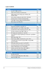
Layout contents
Jumpers
Page
1.
Clear RTC RAM (CLRTC1)
4-5
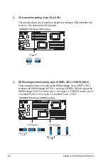
2.
VGA controller setting (3-pin VGA_SW1)
4-6
3.
DDR3 voltage control setting (4-pin LVDDR3_SEL1,
LVDDR3_SEL2)
4-6
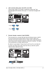
4.
LAN controller setting (3-pin LAN_SW1, LAN_SW2)
4-7
5.
Chassis intrusion connector (2-pin CHASSIS)
4-7
6.
Force BIOS recovery setting (3-pin RECOVERY1)
4-8
7.
IPMI setting (3-pin IPMI_SEL1)
4-8
Internal connectors
Page
1.
Serial ATA connectors (7-pin SATA1–6)
4-9
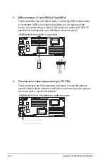
2.
USB connectors (5-1 pin USB3; A-Type USB4)
4-10
3.
Thermal sensor cable connectors (3-pin TR1, TR2)
4-10
4.
Front fan connectors (4-pin FRNT_FAN1–4)
4-11
5.
LPC debug card connector (14-1 pin LPC1)
4-12
6.
Serial General Purpose Input/Output connector (8-1 pin SGPIO1,
SGPIO2)
4-12
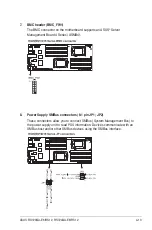
7.
BMC header (BMC_FW1)
4-13
8.
Power Supply SMBus connectors (6-1 pin JP1, JP2)
4-13
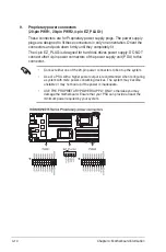
9.
Proprietary power connectors (20-pin PWR1, 20-pin PWR2,
4-pin EZ_PLUG1)
4-14
10.
HDD status indicator header (9-1 pin HSATAT1)
4-15
11.
Hard disk activity LED connector (4-pin HDLED1)
4-15
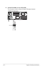
12.
Internal VGA Header (10-1 pin VGA_HDR1)
4-16
13.
Auxiliary panel connector (20-pin AUX_PANEL1)
4-17
14.
System panel connector (20-pin PANEL1)
4-18
Internal LEDs
Page
1.
Standby power LED
4-19
2.
CPU warning LED (ERR_CPU1, ERR_CPU2)
4-19
3.
BMC LED (BMC_LED1)
4-20
Содержание RS720QA-E6/RS12
Страница 1: ...2U Rackmount Server RS720QA E6 RS12 RS724QA E6 RS12 User Guide ...
Страница 20: ...Chapter 1 Product introduction 1 10 ...
Страница 44: ...Chapter 2 Hardware setup 2 24 ...
Страница 50: ...4 2 Chapter 4 Motherboard information 4 1 Motherboard layouts KGNH D16 For RS720QA E6 RS12 ...
Страница 51: ...ASUS RS720QA E6 RS12 RS724QA E6 RS12 4 3 KGMH D16 QDR For RS724QA E6 RS12 ...
Страница 118: ...6 14 Chapter 6 RAID configuration ...
Страница 142: ...7 24 Chapter 7 Driver installation 9 Click your preferred options and click Finish to exit the wizard ...
Страница 148: ...7 30 Chapter 7 Driver installation ...


