background image

page 21

“Status” menu

Operating manual U 158 - 

Version 10-2018A

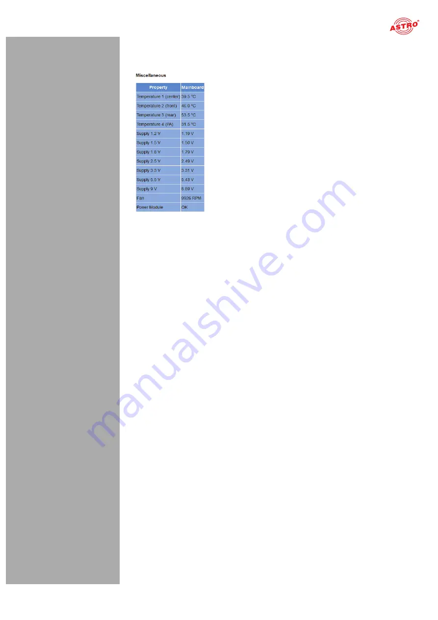
Status messages on temperature, internal voltages and the power module:

Figure 17: Status display - Miscellaneous

The following, general parameters are displayed in the “Miscellaneous” table:

Temperature 1 (center):

 Temperature displayed in °C for the mainboard 

Temperature 2 (front):

 Temperature displayed in °C for the mainboard 

Temperature 3 (rear):

 Temperature displayed in °C for the mainboard 

Temperature 4 (PA):

 Temperature displayed in °C for the HF output stage 

Supply 1.2 V:

 1.2 V supply voltage

Supply 1.5 V:

 1.5 V supply voltage

Supply 1.8 V:

 1.8 V supply voltage

Supply 2.5 V:

 2.5 V supply voltage

Supply 3.3 V:

 3.3 V supply voltage

Supply 5.5 V:

 5.5 V supply voltage

Supply 9 V:

 9 V supply voltage 

Fan:

 Fan rotation speed

Power Module:

 Functional status (OK or error message)

Содержание U 158

Страница 1: ...Version 10 2018A...

Страница 2: ...ation of the U 158 page 09 Status menu page 16 Main menu page 22 Test generator menu page 24 IP channel menu page 26 IP RX menu page 27 RF menu page 29 RF 1 X and RF 2 X menu page 32 TS processing men...

Страница 3: ...k of fatal injuries Warning about various dangers to health the environment and material Warning about thermal dangers risk of burns Recycling symbol indicates components or packaging materials which...

Страница 4: ...accordance with EN 60728 11 and EN 60065 Unqualified person are not allowed to install and start operation of the device Device configuration Target group for the configuration of the ASTRO headend a...

Страница 5: ...he network interface Software versions The version of the plug in module software currently installed is displayed Alarm table The current error messages are displayed RF output The programs currently...

Страница 6: ...information described in this manual The installation site must be planned in a way that prevents children from playing with the device and its connections In order to prevent inadmissible operating...

Страница 7: ...laces in which a leakage of chemicals may occur Organic solvents or fluids in particular may cause the housing and or cables to melt or disintegrate presenting a danger of fire or electric shock They...

Страница 8: ...to establish a mechanical connection between the signal converter and the base unit Both the mains HF connections and the network connections are connected to this backplane There is usually a tempera...

Страница 9: ...en correctly plugged into the corresponding installa tion position will result in incorrect LED displays on the front of the U 100 base unit see section Device description Furthermore the correct posi...

Страница 10: ...uired installation position left middle or right and remove the dummy plate 2 You can now see the two connection cables for the selected slot power supply and signal cable Connect the cables to the ba...

Страница 11: ...m Interface settings is displayed The two management IP addresses Management A and Management B for the device now appear in the upper lines Make a note of the address of the management connection whi...

Страница 12: ...he device display into the address line of the browser The menu page Status will then appear Select the item Log in from the navigation menu at the left The input mask for the log in should then appea...

Страница 13: ...rts being used by activating the corresponding radio button in the line Active To save your changes click on the Submit button below the last table More information on configuring the IP address can b...

Страница 14: ...thernet Data B 8 U158 IP RX1 IP RX2 IP RX3 IP RX4 IP RX IP RX5 IP RX6 IP RX7 IP RX8 TS Sel1 TS Sel2 TS Sel3 TS Sel4 RF1 RF Amplifier RF Attenuator Band Channel Filter Modulator1 Modulator2 Modulator3...

Страница 15: ...u can also enter a source select address in the second line Further information about configuring the receiver can be found in the section Configuring IP inputs There is another table below the IP RX...

Страница 16: ...enu item RF in the web browser interface menu You will now see the following table Figure 12 Configuring HF output channels For an example of this select one of the modulators by clicking on the On ra...

Страница 17: ...8 Version 10 2018A Status menu To have the current settings for the U 158 displayed click on the Status item in the menu at the left You can now see the overview shown in figure 13 Figure 13 Status di...

Страница 18: ...igured here respectively in accordance with the four connections on the backplane of the U 158 Data A Data B Management A and Manage ment B see section Device description MAC MAC address display value...

Страница 19: ...d standard priority cold errors The values set for the following parameters are displayed in the table IP RX channels for the 8 IP re ceivers for outputs Data A and B respectively Prim RX IP socket so...

Страница 20: ...for the QAM modulators 1 and 2 Standard Bandwidth Constellation TS Rate Modulation standard required channel bandwidth BAM constellation output bit rate Standard Bandwidth Constellation TS Rate Modula...

Страница 21: ...d Temperature 2 front Temperature displayed in C for the mainboard Temperature 3 rear Temperature displayed in C for the mainboard Temperature 4 PA Temperature displayed in C for the HF output stage S...

Страница 22: ...rces Information on the internal resources of the operating system can be viewed in the System resources table No settings can be made here File resources Number of left files FOPEN_MAX Number of left...

Страница 23: ...displayed and can be configured MAC MAC address of the respective interface Active Activate the radio button on to activate the interface Activate the radio button off to deactivate the interface Mod...

Страница 24: ...be allocated an address of its own This setting only has to be entered for one module per base unit Slot Address In accordance with the coding of the backplane of the U 158 performed previ ously see s...

Страница 25: ...section Software update and configuration files Clicking the Force Save button saves the configuration with immediate effect The configuration will otherwise only be saved after 10 seconds if no furth...

Страница 26: ...Null packets are generated with a preset packet ID The maximum data rate that can be set totals 67 MBit s Figure 23 Test generator The following settings are displayed and can be configured Data rate...

Страница 27: ...he respective IP inputs here by clicking on the corresponding radio but ton The following parameters are displayed for ports A and B respectively for the four IP input chan nels Prim RX IP socket sour...

Страница 28: ...in the input field This is for example the case when IGMP version 2 or IGMP version 3 from any source is being used as the protocol You can make a priority setting for the primary secondary and tertia...

Страница 29: ...ing RTP UDP IP data streams are received If you activate the radio button on in the line FEC then the additional receive IP ports 2 and 4 will be received example apart from 10000 also 10002 and 10004...

Страница 30: ...be switched off This may be practical when for example the module is being used as a replacement module in a redundant circuit Stream Select the incoming data stream for conversion from the drop down...

Страница 31: ...age appears Once this message has been acknowl edged the maximum value is entered If you change the type of QAM modulation of a pair of output channels the level will be adjusted automatically Channel...

Страница 32: ...level deviation by clicking on the corresponding radio button When the warning message is activated and the level deviation totals 2 5 then the warning message is recorded in the log file and dependin...

Страница 33: ...e changes Click on Reset form to restore the original settings Another table follows in which you can complete all the settings relating to the QAM output signal Figure 31 Modulation table The followi...

Страница 34: ...estore the original settings If you click on the Refresh button all information in the table is updated Another table follows in which you can edit the transport stream Figure 32 Transport stream proc...

Страница 35: ...ansport stream processing You can make settings for the PAT processing NIT processing and the NIT upload here You can activate and deactivate PAT processing for the individual output channels in the P...

Страница 36: ...NIT In line NIT Insertion Interval you can type in the output rate of the NIT in milliseconds 8000 ms for example means that every 8 seconds a complete NIT is generated Remap NIT from PID If a NIT sho...

Страница 37: ...ement Controller should be used for generating a dynamic NIT Click on the corresponding radio button to do so This will update the file nit xml with the Generate from local NIT use NIT 1 mode having t...

Страница 38: ...efresh button all information in the table is updated The table Add External Transport Streams follows You can add an external transport stream here Figure 39 Change network information table The foll...

Страница 39: ...the entries by clicking on the corresponding arrow button in the Sort column To delete an entry activate the respective checkbox in the Remove column Click on the Submit button below the last table t...

Страница 40: ...e LCN Table The LCN Table table follows A list of all the services currently selected appears here To delete an entry from the list activate the checkbox for the respective service in the Remove colum...

Страница 41: ...SSL Settings table In the following table Generate a CSR for this device individual items of information about the device can be entered Certificate Signing Request address organisation etc Figure 44...

Страница 42: ...nd device certificate click the Regenerate button If you change the activation or deactivation status of inputs or outputs in one of the two tables then click on the Submit button below the last table...

Страница 43: ...account activate the corresponding checkbox Delete for the respective account in the right column of the table The following settings can also be entered Timeout You can enter a time for the automati...

Страница 44: ...gurated The RADIUS server must be configurated Users with service type Administrative are admin istrators of the device When the checkbox Enable Radius Login is clicked the RADIUS function is activate...

Страница 45: ...ollowing input mask now appears Figure 50 Transport stream analyzer To analyse a transport stream click on the corresponding radio button in the Analyze line and then click on the Submit button If you...

Страница 46: ...tem in the menu at the left The following input mask now appears Figure 51 Enabling licences using the licence key Now enter the licence key sent to you in the input field The key or keys can be enter...

Страница 47: ...ntent area at the top Figure 52 Firmware update Now click on the Search button and select the path to the memory location of the update archive downloaded beforehand Then click on the Update and Reboo...

Страница 48: ...saving firmware and configurations using T FTP You can update firmware using a T FTP server using the table Firmware update and configuration via server and load or save configuration files Figure 56...

Страница 49: ...n the update archive is unpacked saved to an SD memory card and programmed into the module enter the version number Overwrite backup firmware action The device software is saved in two partitions The...

Страница 50: ...You can check or configure the following parameters individually System log settings Figure 58 Filter settings for the system log display You can activate or deactivate filters for displaying the log...

Страница 51: ...you do not wish for the existing entries to be displayed after a refresh activate the checkbox Check box to clear log on refresh Once the checkbox has been activated after a refresh the process of de...

Страница 52: ...rameters or deactivate the alarm display for a param eter when preferred To do so click on the item Alarm Severities in the menu at the left A set of tables for different parameter groups then appears...

Страница 53: ...item in the menu at the left The following table now appears Figure 62 Active alarm table The table provides information about error messages currently active The Message column shows the error messag...

Страница 54: ...rfaces Management A Management B Data A and Data B Ethernet frames Figure 64 Ethernet frames The following parameters are displayed for the interfaces Data A and Data B in this order The number of IP...

Страница 55: ...umber of frames below this the relative buffer depth in is displayed The buffer depth is displayed in relation to the transport stream rate in the third line FEC If an RTP data stream is being used th...

Страница 56: ...erface statistic properties which are displayed are for information purposes only and are used to describe the network They could be useful for customer service in the event of a fault Documentation m...

Страница 57: ...ory or at workshops or by persons authorised by ASTRO Strobel GmbH Read carefully EN 60728 11 Safety requirements No service work during thunderstorms HINWEIS In the event of repairs DIN VDE regulatio...

Страница 58: ...Data rate adjustment PCR correction NIT handling PID remapping Output symbol rate Msymb s 3 45 7 5 for 2 adjacent channels Bandwidth MHz 4 8 depending on output symbol rate Brutto data rate Mbit s 55...

Страница 59: ...Technical data page 59 Operating manual U 158 Version 04 2018A...

Страница 60: ...r in full without prior agreement of the ASTRO company These operating instructions have been written by ASTRO Strobel Kommunikationssysteme GmbH Olefant 1 3 D 51427 Bergisch Gladbach Bensberg Tel 022...

Отзывы: