background image

10 


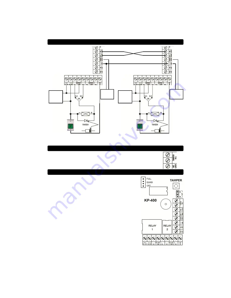
INTER-LOCK SYSTEM WIRING DIAGRAM 

12 OR 24V 
AC OR DC 

POWER 

SUPPLY 

AC POWER 

CAN ONLY BE USED 

WITH 

AC POWERED 

ELECTRIC STRIKES 

MAGNETIC LOCK 

OR 

ELECTRIC STRIKE 

MODEL TS-2 

REQUEST TO  

EXIT STATION 

(OPTIONAL) 


USE N/O CONTACTS 

N/C 

DOOR 

CONTACT 

12 OR 24V 
AC OR DC 

POWER 

SUPPLY 

AC POWER 

CAN ONLY BE USED 

WITH 

AC POWERED 

ELECTRIC STRIKES 

MAGNETIC LOCK 

OR 

ELECTRIC STRIKE 

MODEL TS-2 

REQUEST TO  

EXIT STATION 

(OPTIONAL) 


USE N/O CONTACTS 

N/C 

DOOR 

CONTACT 

Two keypads are required for an inter-lock system. If either door is open, the other door 
will  remain locked. 

TAMPER SWITCH 

The Tamper Switch is Normally-closed when the keypad face plate is 
securely attached to the back box. Connect these terminals to an alarm 
panel if desired. 

BACKLIGHT ADJUSTMENT 

The keypad has an adjustable backlight feature. The 
backlight illumination can be set to “FULL”, “QUASI”, and 
“OFF” using the jumper located in the upper left hand corner 
of the PCB assembly behind the front plate. 

Содержание Alarm Controls KP-300

Страница 1: ...00 645 5538 www alarmcontrols com Model KP 400 is a self contained vandal resistant digital keypad This dual relay output keypad is suitable for residential industrial and commercial installations It...

Страница 2: ...ed tool 2 Pass the wire harness through the opening in the back box 3 Mount the back box to the door frame or wall 4 Make all required wiring connections to the terminal blocks 5 Place the keypad face...

Страница 3: ...put that switches to ground after the duress code has been entered Output rating Ic max 100mA sink Vc max 24VDC Door Position Sensor Input DOOR SENS A normally closed contact connected to this termina...

Страница 4: ...Programming Mode in order to access all keypad configuration settings 1 Put the keypad in Program Mode by entering the Installer Code followed by the The keypad will beep twice and the yellow LED wil...

Страница 5: ...tering the Installer Code followed by the The keypad will beep twice and the yellow LED will be on and not blinking 2 Enter 7 2 5 3 Enter to exit Program Mode The yellow LED will begin blinking To dis...

Страница 6: ...s 1 and 2 can be programmed for either momentary or latching operation Momentary operation time can be set for between 1 and 999 seconds The factory default momentary operation time is 2 seconds 1 Put...

Страница 7: ...ep twice and the yellow LED will be on and not blinking 2 Enter 8 2 1 3 Enter to exit Program Mode The yellow LED will begin blinking To return the keypad to Manual Entry Mode 1 Put the keypad in Prog...

Страница 8: ...new installer code For example if you wish to change the Installer Code to 1 2 3 4 you would enter 0 1 2 3 4 7 The keypad will beep twice indicating that the new Installer Code has been accepted 8 Ent...

Страница 9: ...DC POWER SUPPLY AC POWER CAN ONLY BE USED WITH AC POWERED ELECTRIC STRIKES MAGNETIC LOCK OR ELECTRIC STRIKE MODEL TS 2 REQUEST TO EXIT STATION OPTIONAL USE N O CONTACTS Output 2 is used to control acc...

Страница 10: ...2 REQUEST TO EXIT STATION OPTIONAL USE N O CONTACTS N C DOOR CONTACT Two keypads are required for an inter lock system If either door is open the other door will remain locked TAMPER SWITCH The Tampe...

Страница 11: ...5 Relative Humidity Non condensing Environmental Rating Conforms to IP66 Dimensions 3 125 W x 4 5 L x 1 75 to 2 5 D CODES It is recommended that the Installer Code and User Codes be noted here for ref...

Страница 12: ...KP 400 Rev E 3 14...

Отзывы: