32
For installation of two machines
To avoid having to extend the drain hose,
we recommend that the machines be posi-
tioned either side of the sink, where possi-
ble.
If you do decide to place the machines side
by side, the drain hose may be extended by
a maximum of 3 metres. Total length 4.5 me-
tres.
CAUTION!
Connection to electricity, water and drain-
age must be carried out by a suitably quali-
fied person.
Connection to the drain
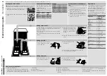
The drain hoses can be routed to connec-
tion nipples at the sink unit’s water trap (see
illustration 4). Please note that the hoses
must be attached at the same height as the
underneath of the sink unit – otherwise the
dishwater from the sink may run down into
the dishwasher.
The drain hoses are threaded onto the
cone-shaped connecting pipes at the sink
unit’s water trap. The cone-shaped pipes
must be cut to an internal diameter of at
least 16 mm.
If there is only one connection point at the
sink, an accessory kit containing a Y-
shaped pipe and two non-return valves can
be ordered.
Installation is performed as per illustration 1.
The drain hoses may be extended by a
maximum of 3 metres (the total length of the
drain hose must not exceed 4.5 metres).
Any connections and connecting pipes
must have an internal diameter of at least
16 mm. However, the drain hose should ide-
ally be replaced with a new hose without
joins.
No part of the drain hoses may be more
than 950 mm above the bottom of the ma-
chine.
The hoses must not be routed directly to the
floor drain or similar. In such cases, the
hoses can act as a siphon and empty the
machine.
The hose must always discharge at least
350 mm above the bottom of the machine.
Water connection
A T-piece coupling is mounted on the inlet
pipe after the stopcock.
The stopcock should be positioned on top
of the sink unit or at the front of the sink unit
cabinet.
This is done to avoid having to cut off the
water at two separate points.
In placing the machines side by side, it may
be necessary to extend the inlet pipe.
The inlet pipe has a coupling with either a
1/2” or 3/4” internal thread, depending on
the country.
Once installation is complete, the stopcock
should be opened to allow the pressure to
settle for a while and to check that all con-
nections are tight.
M
a
x 950 mm
M
in 350 mm
Min 16 mm
M
a
x 950 mm
M
in 350 mm
Illustration 4
Содержание D3720
Страница 2: ...2 ...
Страница 38: ...38 Own comments ...


