


17.
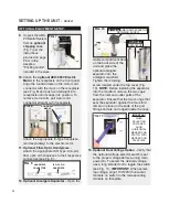
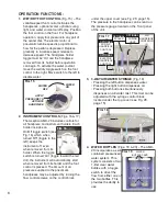
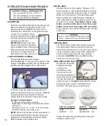
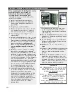
WASTE REMOVAL:
Routinely empty
the waste contain-
er daily. To empty
the waste system,
connect the waste
hose elbow to
the waste dis-
charge on the
back of the unit by
inserting the elbow
until it locks into
place. Switch on
the waste purge pump to empty the waste system.
To disconnect the waste hose, depress the button on
top of the waste discharge to release the waste hose
elbow.
IMPORTANT:
The waste hose must be connect-
ed to the waste discharge to enable pump switch oper-
ation.
NOTE:
Amalgam separators (optional equipment)
require no settlement time before draining the waste
tank. Replace the amalgam separator annually or soon-
er if it becomes full of particulate and impedes waste
tank discharge. Replacement amalgam separators (PN
730595) are available through Aseptico. Refer to the
label on the amalgam separator for the address of an
approved amalgam recycler.
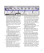
AIR TANK PURGE:
Routinely purge the air tank once a day to remove
condensation from the air storage tank.
PURGING WATER FROM THE SYSTEM:
Purge all water from the system if the unit will be
unused for more than a week or exposed to freezing
temperatures. Empty both water bottles, then reinstall
them into their caps. Rotate open (counter-clockwise)
all water coolant knobs (open knobs fully for fastest
purging). Toggle on all instrument holder switches.
Switch on the main power. Toggle on the bottle
pressure switch. Purge all water lines simultaneously
or one at a time: Hold handpieces and scaler over a
basin while holding the flush toggle switch in the on
position until all water is purged from the lines with air.
Finally, hold the water syringe over the basin and hold
down the water button until all water is purged from
the line with air.
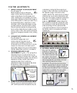
GENERAL CLEANING:
The external surfaces of the chassis should be
cleaned using a soft cloth moistened with a mild
detergent solution. Any external surfaces of the unit
that are contacted during use should be wiped down
with a soft cloth moistened with a disinfectant at the
beginning of each day and between each patient use.
D
C
A
B
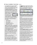
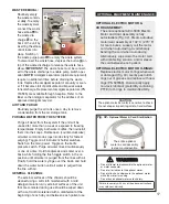
OPTIONAL EQUIPMENT MAINTENANCE:
OPTIONAL ELECTRIC MOTOR &
CORD ASSEMBLY:
The entire optional AEU-5000 Electric
Motor and Cord Assembly is fully
autoclavable (Fig. 32). Steam autoclave
motor/cord assembly at 132° C (270° F)
for ten minutes. Loosely coil the motor
cord when autoclaving. Avoid sharply
bending the cord when autoclaving.
Alternatively, wipe down the motor cord
with disinfecting solution, and/or sleeve
the cord between each patient.
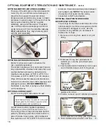
OPTIONAL ELECTRIC MOTOR O-RINGS:
Replace electric motor O-rings when worn
or damaged (Fig. 33). Gently peel old O-
rings out of grooves and replace with new
rings (PN 520069). Occasionally apply
non-toxic lubricant (preferably containing
PTFE) to O-rings to maintain flexibility.
The entire optional
motor & cord assembly
is steam autoclavable.
Fig. 32 -
Optional Motor & Cord Sterilization
• Do not attempt to disassemble the optional motor
or motor connector.
• Do not oil or lubricate the optional motor.
• Do not attach a handpiece to the optional motor
while the motor is running.
• Do not bend optional motor cord sharply.
WARNING
Failure to comply with any of the above instructions
may void your warranty.
CAUTION:
The optional electric motor is sensitive to shock.
Do not drop or impact it against a hard surface.
C
A
B
D