


14.
OPTIONAL EQUIPMENT FUNCTIONS -
Cont’d:
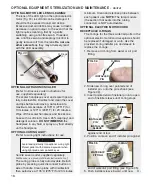
the foot pedal will turn the light Off. The
light is cooled with drive air from the AMC-
20 manifold at 20 psi. An audible tone will
sound every 10 seconds while the light is
active.
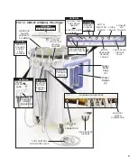
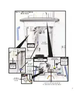
18. OPTIONAL AMALGAM SEPARATOR
(Fig. 14, page 7) – The amalgam separator
is located in the rear waste compartment.
The separator allows for particulate from the
waste compartment to be trapped prior to
being pumped out of the unit. The separator
can be replaced by unscrewing the knob
located under the top cover, and removing
the filter from the waste compartment.
CAUTION:
Observe local regulations
concerning disposal of amalgam waste.
19. OPTIONAL WASTE FLOW CONTROL
(Figs.
14 & 30, pages 7 & 15) The waste flow control
is located in the rear waste compartment. This
valve allows for the adjustment of the waste
pump flow rate, to meet a State’s or Country’s
regulatory requirements for wastewater filtering
and collection (refer to para. 5, page 15).
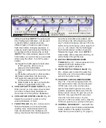
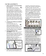
20. OPTIONAL ACCESSORY TRAY
(Fig. 27)
The height of the optional accessory tray
can be adjusted: remove the tray and arm
from the pivot block, then use the 3/16"
Allen wrench (supplied) to loosen the hex
screw and reposition the block to the
desired height. The tray and arm also pivot
horizontally.
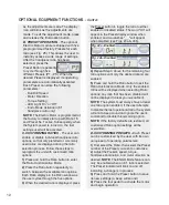
electric scaler system that provides
adjustable ultrasonic levels and a water
coolant system. The scaler includes 3
instrument tips: The #37 instrument is
specially developed for subgingival scaling,
furcations, supragingival fine scaling and
spot removal. The #38 tip is used for
lingual and buccal subgingival scaling and
furcations. The #39 tip is used for universal
lingual and buccal supragingival scaling.
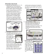
The scaler is controlled by the scaler
ultrasonic setting adjustment knob which is
located on the left side of the front panel
(see Fig. 26). The ultrasonic intensity can
be adjusted by turning the control knob
clockwise to maximum or counterclockwise
to minimum. When scaling, follow the tip
manufacturer's recommended ultrasonic
settings for each tip.
The coolant level is controlled by the
scaler coolant flow adjustment knob (see
Fig. 28, page 15). Turn knob
counterclockwise to increase coolant flow;
turn clockwise to decrease coolant flow.
17. OPTIONAL CURING LIGHT
(Fig. 17, page
8) - The AMC-20 offers an optional LED
curing light. When the light is removed
from the holder and the foot pedal is
depressed, the light turns On. Releasing
FIG. 26
SCALER ULTRASONIC CONTROL
SWITCH
Verify that scaler coolant flow
of no less than 20ml/min is
available at the tip.
SEE ACCOMPANYING SCALER
DOCUMENTS
WARNING:
Avoid looking directly into Curing Light. Protect
patient with darkened eyewear when using light
probe near patient's eyes.
FIG. 27
PIVOT
BLOCK