


Page 4
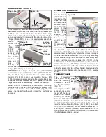
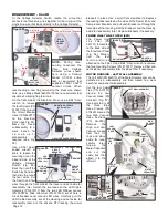
peel the large Outer Foam Pad (PN 730685), Inner Foam
Pad (PN 730684), or circular Tube Foam Pan (PN 730687)
off their Mounting Studs (PN 510848) and Velcro Strips (PN
480030) (Fig. 11). Clean or replace pads as needed and
then reattach to frame.
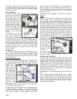
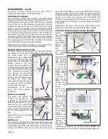
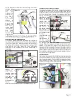
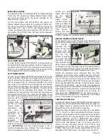
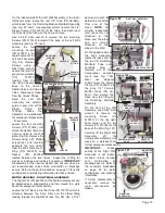
WASTE TANK ASSEMBLY
The Waste Tank is located on the back side of the Transport
III, hanging from a mounting bracket on the case lid (Fig. 12).
First, remove the four gray hoses from the top of the waste-
tank lid. Note the color match between the black and white
rotating latches on the
lid with their respective
black or white hose
fittings. Also note that
the HVE and saliva-
ejector
instrument
hose fittings are keyed
to only fit their
respective inlet ports.
Unplug the waste level
sensor
from
its
connector on the
Electrical
Panel
Assembly (see Fig. 9).
Ensure that the tank
has been cleaned of all waste and residue before removing
(refer to Operations Manual for instructions on emptying the
Waste Tank.) Lift Tank off mounting bracket and set aside for
reassembly later.
WATER BOTTLE
Release any residual pressure from the Transport III Water
Bottle by toggling the Pressure Release Valve to the right
(Fig. 13). Unscrew the Water Bottle from its cap and carefully
lower the bot-tle until clear of its water-supply tube/ filter
assem-bly. Place Bottle aside for reassem-bly later.
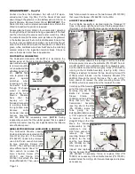
DISASSEMBLY
OVERVIEW:
When disassembling the AEU-525CF
Transport III System, it is recommended that its modular
subassemblies be removed and disassembled in the order
shown below:
1. Inlet/Outlet Air Filter Assy
2. Waste Tank Assy (*)
3. Dental Instruments
4. Water Bottle
5. Air/Electric Module Assy (*)
6. Air Bottle Assy
7. Top Shelf Components
8. Electrical Panel Assy
9. Motor Housing - Left Wall Assy
10. Motor Housing - Right Wall Assy
11. Venturi & Muffler Bracket Assy
12. Compressor/Vacuum Pump Assy
13. Case Assy
(*) The Waste Tank and Air/Electric Manifold Block are not
customer-serviceable subassemblies and should not be
disassembled in the field -- please return these items to
Aseptico if repairs are necessary.
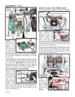
The operator control panels are located on the Air/Electric
Module Assembly. The power inlets and power supplies are
located on the Electrical Panel Assembly, and the
compressor and its vacuum components are located on the
Motor Housing Assembly.
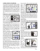
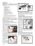
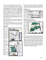
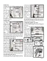
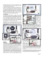
INLET/OUTLET AIR FILTER ASSEMBLY
The socket for the Waste Tank Level Sensor Connector is
located on the Electrical Panel Assemby, behind the Air
Filter Assembly (see Fig. 9).
Grasp the locking collar on the Connector and pull the
Connector straight out of its socket, through the plastic hole
in the Air Filter Assembly. The Connector is keyed to the
socket, so when
reinstalling, press the
connector
gently
against the socket
then rotate until the
connector aligns with
and enters the socket.
Ensure
that
the
connector is dry and
free of any moisture
before reconnecting to the socket.
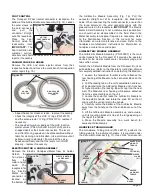
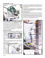
Swing the Connector and cord out of the way. Use either a
standard flat-head screwdriver, or the fastener tool provided
on the inside of the Transport III case lid, to loosen the four
fasteners on the Filter frame (Fig. 10). Turn the fasteners
counter-clockwise 1/4-
turn. Lift the Filter out
of the lid door frame
and move to a
workbench for further
disassembly.
The three foam filter
pads can be detached
from the Filter frame
for
cleaning
or
replacement. Carefully
Figure 11
OUTER
FOAM
PAD
TUBE
FOAM PAD
WASTE
SENSOR
SOCKET
Figure 9
WASTE SENSOR
CONNECTOR
FILTER
FASTENERS (4)
Figure 10
KEYWAY
Figure 12
ROTATING
LATCH
INNER FOAM
PAD
VELCRO
MTG STUD (X10)
HVE
HOSE
SALIVA
EJECTOR
HOSE
MOUNTING
BRACKET
Figure 13
WATER BOTTLE
CAP
PRESSURE
RELEASE
VALVE
(RELEASE)