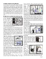

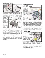

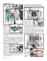
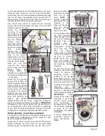


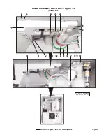

Locate the Cable Tie (PN 510137) that straps the Display
Module
Power
Cable (PN 875118)
to the Compressor
Assembly (see Fig.
77). Cut the Tie to
provide additional
slack for the Power
Cable.
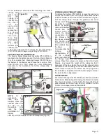
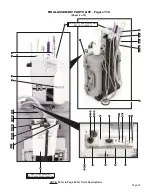
Carefully rotate the
C o m p r e s s o r
Assembly onto its
back side (see Fig. 78) (Place a protective pad under the
Assembly to prevent scratching.)
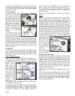
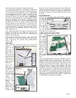
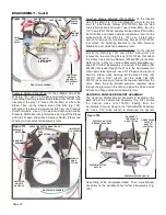
MOTOR HOUSING COVER
Locate the four mounting Screws that attach the Motor
Housing Cover to the Compressor Assembly (see Fig. 78).
Use a 5/64" Allen wrench to remove the Screws (PN
510160), metal Washers (PN
510431), and Rubber Washers
(PN 510827). Carefully lift the
Cover off the Compressor
Assembly and set aside until
reassembly later (see Fig. 79)
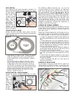
510037) that mount the
Panel to the Compressor.
Remove Panel (see Fig.
73) and place aside for
reassembly later. If the
Handle (PN 850075) on the
Panel needs replacment,
use a 4mm Allen wrench to
remove the two mounting
Screws (PN 510717) and
Lockwashers (PN 510420).
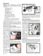
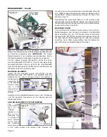
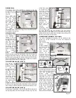
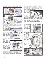
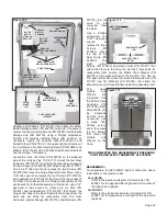
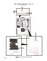
VACUUM HOSE FITTINGS
Locate the Air/
Electric Manifold
Door on top of the
Case. Open Door to
access the High and
Low Vacuum Hose
end Fittings inside
the Bulkhead Insert
(Fig. 74a). Use
adjustable channel
lock pliers to pry off
the Ferrule (PN
462138) and then
the Fitting (PN
462021) on the
larger High Vacuum
Hose (PN AA-259)
(see Fig. 73b). Inspect O-Ring (PN 520101) for wear and
replace if necessary. Next, remove Ferrule (PN 462139) and
Fitting (PN 462022)
on the Low Vacuum
Hose (PN 730489)
(Fig. 73b). Inspect
O-Ring (PN 520100)
for wear and replace
if necessary. Pull
both Vacuum Hoses
ends down through
the Bulkhead Insert. Leave opposite ends attached to the
Compressor Assembly (Fig. 75).
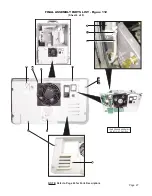
BULKHEAD TUBES
Use diagonal cutters to pry off the 1/8" & 1/4" Tube Sleeve
Clamps (PNs 730015 & 730095) (Fig. 76). Then, remove the
Red Tube (PN AA-94R), Green Tube (PN AA-94G), and
Gray Tube (PN AA-96) from their fittings. Leave the opposite
ends of the Tubes attached to the Compressor Assembly.
Page 14
DISASSEMBLY - Cont’d
Figure 77
Figure 74a
LOW VAC
HOSE
HIGH VAC HOSE
Figure 74b
LOW VACUUM
HOSE FITTING
HIGH VACUUM
HOSE FITTING
(FERRULES)
(O-RINGS)
BULKHEAD
INSERT
CABLE
TIE
DISPLAY MODULE
POWER CABLE
Figure 78
DISPLAY
MODULE
PWR CABLE
MTG. HARDWARE
(X4)
(MOTOR HOUSING COVER)
ROTATE
COMPRESSOR
ASSEMBLY
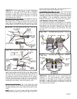
Figure 79
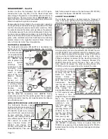
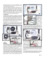
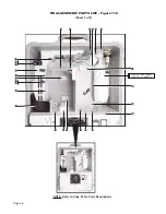
ELECTRICAL PANEL
MOTOR HOUSING COVER
DISPLAY MODULE
POWER CABLE
24V PWR SUPPLY
CONNECTOR
48V PWR SUPPLY
CONNECTOR
CABLE TIE (X4)
GROUND WIRE
MTG NUT
Figure 80
Figure 73
(TOP PANEL REMOVED)
Figure 75
VACUUM
HOSES
COMPRESSOR ASSY
1/8" TUBES 1/4" TUBE
SLEEVE CLAMPS
Figure 76