


Page 50
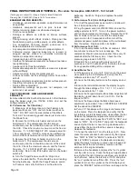
FINAL INSPECTION AND TESTING -
Procedure for Aseptico AEU-525CF - F-4.10-02-B
(Testing specs subject to change. Refer to latest Schematic
Drawing Set, PN 420991, Sheets 16-18 for updates.)
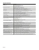
EXAMINATION FOR DEFECTS:
• Unit design, construction, operation, and performance not
as specified.
• Hardware components such as pins, screws and
fasteners missing, broken or otherwise damaged.
• Finish not as specified.
• Damage or defects on exterior or interior surfaces
present.
• Plating missing which effects function. Plating not free
from blisters, peeling, visible porosity, or other defects.
• Any component fractured, broken punctured, torn,
bowed, deteriorated, or malformed.
• Any component misplaced or not in proper alignment.
• Fastening device requiring loosening or removal is
swaged, peened, staked, or otherwise permanently
fastened, components missing.
• Components do not fit or mate properly.
• Interface fits between components not proper (too loose;
too tight/binding).
• Components not free from defects.
• Removable components cannot be removed or replaced
without difficulty.
• Coarse machine, tool or die marks present.
• Surface not clean, not free of foreign matter, flux or other
defects.
• Damage or defects on exterior or interior surface present.
• Operating instructions not provided.
• Service data not provided.
• Identification markings not present, not complete, not
permanent, not correct.
TEST PROCEDURE - NEW AND REPAIRED
PRODUCTS:
A.
Assemble AEU-525 with all instruments in their holders,
plug the power cord into 115VAC, 60Hz, and set the
voltage selector to “115”.
B. Performance Test (Suction):
1.
Make sure all instruments are in their holders, and
power switches are “ON”, and turn holder switches to
“OFF”. DO NOT latch the side latches of the Waste
Tank Lid. The Lid sealing gasket should just rest on top
the Waste Tank.
2.
Remove the HVE from its holder and turn on the
holder switch. The compressor should come on
continuously and there should be vacuum at the end of
the HVE. Check the maximum vacuum and the free air
flow rate. If < 3.9 SCFM @ 54” WC, remove power for
1 hour and repeat. If still low, mark as non-conforming.
Return HVE to its holder and turn the holder switch off.
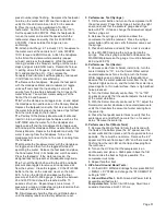
3.
Remove the LVE from its holder and turn on the
holder switch. The compressor should come on
continuously and there should be vacuum at the end of
the LVE. Check the maximum vacuum and the free air
flow rate. If < 1.2 SCFM @ 20” WC, mark as non-
conforming. Return LVE to its holder and turn the holder
switch off.
4.
Turn the Purge/Pressure switch to ‘Purge’ and
remove the water bottle. There should be no air leaking
from the bottle cap. Switch the Purge/Pressure switch
to ‘Pressure’ and verify that there is air flow from the
bottle cap. Switch to ‘Purge’ and replace the water
bottle.
C. Performance Test (Line Voltage Select):
1.
Turn off the compressor power switch and allow all
the air to bleed from the system.
2.
Plug the power cord into 230VAC/50Hz and set the
voltage selector to “230”. Turn on the power switches
and run the compressor until it stops. Remove the HVE
from its holder and turn it on to start the compressor
again and run for 15 seconds and then turn off the
compressor power switch and allow all the air to bleed
from the system. Replace HVE in its holder.
D. Performance Test. (Air):
1.
Turn on the compressor to fill the air reservoir. Wait
two minutes to ensure there is no leakage. The
compressor should not come on sooner than every 30
seconds after the first two cycles. Check that the
pressure gauge reads 45-55 PSI.
2.
Operate the air syringe with a duty cycle of 20
seconds on and 10 seconds off for 5 minutes to check
for any possible stalling of the compressor.
E. Hand Motor Test:
1.
If the power is on, turn it off. Now turn on the power
while watching the LCD display and verify that the
software versions are “127” and “11”.
2.
Ensure the Standby button turns the display on and
off.
3.
Ensure the ratio button causes the display to cycle
through the ratio settings of 1:5, 1:2, 1:1, 5:1, and 8:1.
Set the console to the 1:1 ratio.
4.
Ensure the Torque Adjust buttons allow adjustment of
the display up and down from 5% to 100%. Set the
torque to 100%.
5.
Ensure the Speed Adjust buttons allow speed
adjustment up and down from 2.00KRPM to 40.0KRPM.
Set the speed to 2.00KRPM.
6.
Put a 20:1 handpiece with a large bur of some kind
on the motor. Press the footpedal and verify that the
bur rotates counterclockwise when viewed from the bur.
Release the footpedal and press the motor direction
button and verify that it goes from “FWD” to ”REV” and
back to “FWD”. Set it to “REV” and press the footpedal
and verify that the bur is now turning clockwise when
viewed from the bur and that the console is beeping.
Release the footpedal.
7.
Change the ratio to 8:1 and the torque to 5%. Now
press the motor direction button and verify that it goes
from “FWD” to ”REV” to “ENDO” and back to “FWD”.
Set it to “ENDO” and press the footpedal and loosely
grasp the slowly turning bur until you hear a beep and
the direction of the bur will briefly reverse and then
continue in the original direction.
8.
Remove the handpiece and press the “sun” symbol
until the LED turns on. Press the Torque Adjust buttons
to verify that the light intensity varies from very bright to
much dimmer. Leave the intensity at 100% and press
the “sun” symbol to turn off the LED. Press the “sun”
symbol to turn on the symbol on the LCD display and
press the “PRESET” button until there is a beep and the