Operating Manual
GageMux® USB
www.SPCcanywhere.com
(248) 370-9919
11
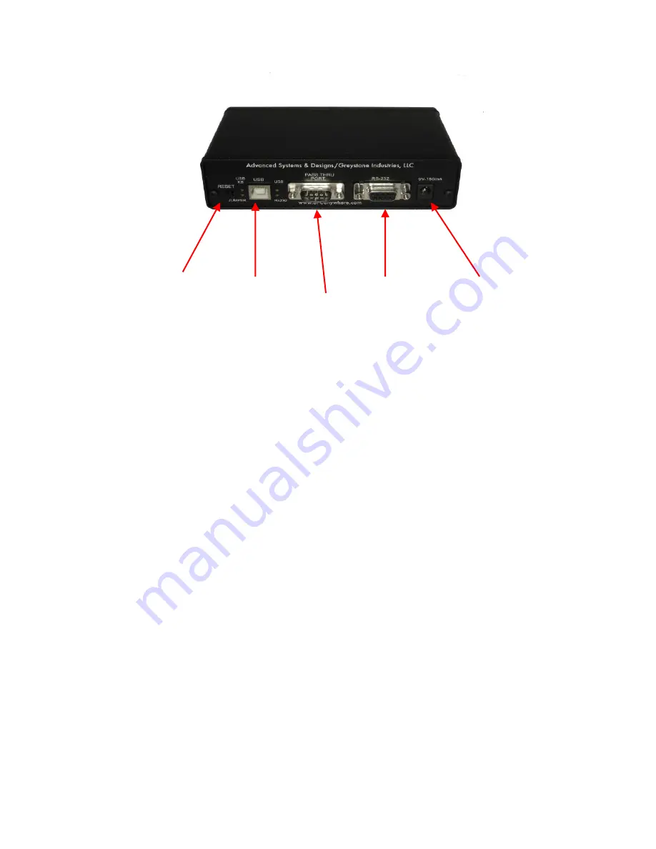
Reset Pushbutton USB Output RS232 Output
9 volt DC Supply Jack
Daisy Chain/Pass Thru Port
Figure 2; GageMux® USB Rear Panel
The rear panel has three components: The pushbutton reset switch, one
USB male connector, one 9- pin female RS-232 serial connector, another 9
pin male RS-232 pass-thru connector, LED lights for each output mode
(USB, RS232, and USB Keyboard), USB Power and the 9 volt power
supply jack.
Basic Operation
The basic operation of the GageMux® USB is straightforward. The
following steps demonstrate the standard method to get your GageMux®
running:
1.
Out of the box the unit is configured to run in Normal mode. You
may change this mode by either changing the rotary switches or
using the E-commands or temporary host commands. (See the
“Configuration and Setup” section below for details).
2.
Connect one end of the USB cable to the PC and the other end to
the GageMux USB.
3.
If you would like to use RS-232 connection, then connect a RS-
232 serial cable to the serial device (i.e. computer or printer).
4.
Connect your gages and foot switches to the GageMux® USB.
5.
Connect the 9-volt DC power supply into the 8-port GageMux®
USB and plug the power supply into a 110 volt AC outlet. The
USB Cable included will provide power to the 2 & 4-port
GageMux®.
6.
Press the reset button. On the ports with active gages the LED will
light green. Inactive or empty ports will light the red LED.
Содержание GageMux 500-20-USB
Страница 1: ...Operating Manual GageMux USB 2 4 8 Input Gage Interface...
Страница 4: ...Operating Manual GageMux USB www SPCcanywhere com 248 370 9919 4...
Страница 6: ...Operating Manual GageMux USB www SPCcanywhere com 248 370 9919 6...
Страница 50: ...Operating Manual GageMux USB www SPCcanywhere com 248 370 9919 50...


