P/N PM000223A • Rev. 1 • ISS 9 August 2017
78
Installation Manual
NU-Series Hardware
Room Modules
3 of 4
P/N PM000194A • Rev. 1.00 • ISS 4/3/17
“TOP” (printed on the inside of the spacer) is pointing up
and that the spacer is level. Use a leveling device to check,
if necessary.
2. Using the spacer as a template, mark four holes for the
screws using the outer fitting holes located in the corners
of the spacer.
3. Remove the spacer and drill screw holes for the screws
that will be used, such as wood, concrete, or drywall
screws, or screws with anchors.
4. Remove the knock outs in the spacer for the cable wires.
5. Place the spacer over the holes, insert the screws, and then
tighten.
6.
Pull the cables though the knock out holes
.
To make the connections to the module:
1. Pull the cables from the backbox and pull through the
adapter.
2. Mount the module’s adapter to the backbox.
3. Slide the frame over cables.
4. Insert the 6-pole interconnection cable for the NUSB3X
Bedside Extension module through the knockouts in the
backbox, and then attach the cable to the 6-pin terminal.
The interconnection cable is included with the module.
5. Attach the 4-pole connector cable for the Television
Interface module (NIAT) to the 4-pin terminal.
6. Attach the 4-pole connector cable from any compatible
third-party device to the 4-pin auxiliary terminal.
7. Mount the module to the backbox or spacer.
Note: The 4-pole block connectors are not supplied
with the module. They are available as accessories and
must be ordered separately.
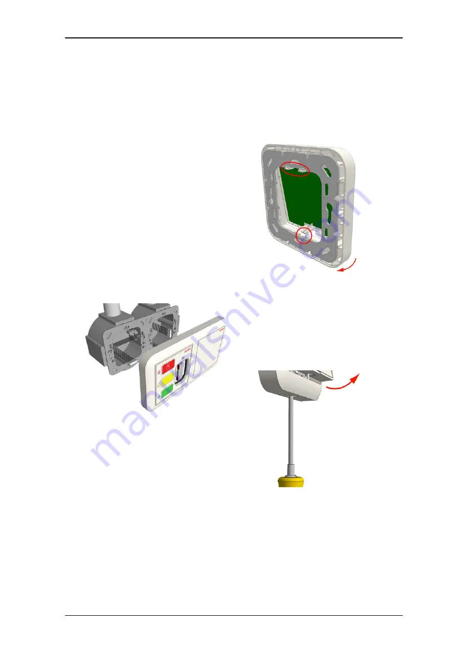
To attach the module on the adapter:
1. Place the module against the frame, ensuring that
the module is facing up.
2. Place the module’s upper snap fasteners against
the upper edge of the adapter.
3. Press the module firmly against the adapter so
that the module’s bottom fasteners snap closed on
the adapter. See previous figure.
Removal
When separating the module from an adapter or spacer,
use a screwdriver with a blade that is approximately 6mm
wide.
To remove the module from a backbox or spacer:
1. Insert the #2 flat blade screwdriver into the slot at
the bottom of the module between the faceplate and
the adapter.
2. Gently push the #2 flat blade screwdriver until the
module releases from the adapter.


