PREPAIRING THE GRINDER MIXER FOR OPERATION
15
PREPAIRING THE GRINDER MIXER FOR OPERATION
Remove the shipping banding or wire from the
auger feeder (if equipped), rear discharge cover
and the unloading tube to saddle at the side of the
tank.
IMPORTANT:
Remove
the
bag
from
the
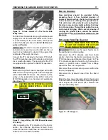
supplement hopper. Place the screen hook in the
hammer mill door pin (See Figure 9).
Figure 9 - Screen Hook Storage.
Install the PTO driveline storage bracket under the
front hitch with 1/2 inch x 1-1/2 inch bolt and lock
nut (See Figure 10). Maintain tension with the lock
nut to allow movement with 15 lbs. pull.
Figure 10 - PTO Driveline Storage Bracket.
Refer to OPERATION OF GRINDER MIXER
–
Auger Feeder Operation.
Install any option that was ordered with the grinder
mixer and shipped as loose equipment. See
instructions packaged with the specific options for
installation.
Install the implement end of the PTO driveline by
fastening it to the input jackshaft with the 5/16 inch
x 3-1/2 inch clevis pin and cotter pin provided.
Spread the cotter pin and make sure the proper
PTO is used.
CAUTION: NEVER OPERATE A 540 RPM
GRINDER MIXER WITH A 1000 RPM
TRACTOR.
If equipped with a bolt-on extension, hydraulic
auger feeder, or roll feed, refer to OPERATION OF
GRINDER MIXER
Auger Feed Operation sections as well as the
ATTACHMENTS section for instructions.
T
IRES
Keep tires properly inflated. Lack of pressure can
result in torn valve stems, fabric breaks and uneven
tread wear. Too much pressure can cause undue
strain on fabric, excessive tread wear and allows
the tire to cut in more on wet surfaces. Equal tire
pressure reduces grinder mixer sway when towing.
Recommended tire inflation pressure is as follows:
9.5L x 15
8
– ply tires – 44 psi
G
UARDS
,
D
OORS
,
A
ND
S
HIELDS
Make sure that all of the guards, doors, and shields
are in place and functioning.
B
OLTS
A
ND
N
UTS
Cap screws, except for shear bolts, used on the
grinder mixer are Grade 5 and if replaced, cap
screws of equal or greater strength should be used.
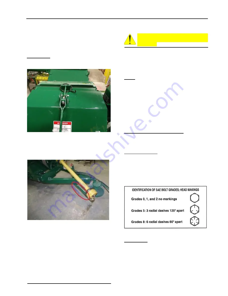
Grade 5 cap screws are identified by three radial
dashes on the hex head. Refer to the SAE bolt
identification guide (See Figure 11).
Figure 11 - SAE Bolt Identification.
IMPORTANT:
Shear bolts must be replaced with
bolts of the same grade
Before operation of the grinder mixer, make sure all
bolts and nuts are properly tightened. Make sure all
cotter pins are spread and not damaged. After
operation of the grinder mixer for several hours,
make sure all bolts are set to proper torque. Refer
to the torque guide (See Table 1).
Содержание JR Series
Страница 7: ...TABLE OF CONTENTS 5 ...
Страница 29: ...GRINDER MIXER ADJUSTMENTS 27 Figure 42 Discharge Auger Drive Chain Shield Removed for Clarity A B C D B C D ...
Страница 34: ...32 LUBRICATION Figure 60 Wheel Bearing Lubrication ...
Страница 42: ...40 SCHEMATICS SCHEMATICS TRACTOR HYDRAULICS ...
Страница 44: ...Art s Way Manufacturing Co Inc Hwy 9 West PO Box 288 Armstrong IA 50514 U S A ...


