IL6000 Chassis Installation and Operations Manual
5
Chassis Overview
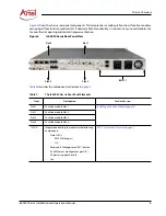
shows the chassis rear panel components. This sample chassis configuration shows function modules
occupying all four function module slots. If needed, a blank module tray is inserted in any unused module slot
to cover the slot opening and maintain proper ventilation.
Figure 2.
IL6000 Chassis Rear Panel View
describes the components called out in
.
Table 2.
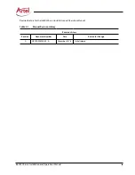
The IL6000 Chassis Rear Panel Elements
Item
Description
for details, see...
Slot 1
Function module Slot 1
Installing a Function Module (page 13)
Slot 2
Function module Slot 2
Slot 3
Function module Slot 3
Slot 4
Function module Slot 4
ILM121
Integrated assembly that contains the following
components:
•
Status LEDs:
–
EMS (IL Manager)
–
OK
•
Recessed IL Manager reset (RST) button.
•
RJ-45 Ethernet management ports (2)
•
AC power supplies A and B
•
Fan
ILM121 Assembly Overview (page 6)
Slot 4
Slot 2
Slot 3
Slot 1
ILM121
Содержание InfinityLink IL6000
Страница 1: ...WWW ARTEL COM Manual Installation and Operations Manual INFINITYLINK IL6000 Chassis...
Страница 2: ...ii IL6000 Chassis Installation and Operations Manual...
Страница 4: ...iv IL6000 Chassis Installation and Operations Manual...
Страница 11: ...IL6000 Chassis Installation and Operations Manual xi...
Страница 31: ...18 IL6000 Chassis Installation and Operations Manual...
Страница 33: ...Index Index 2 IL6000 Chassis Installation and Operations Manual...
Страница 34: ......


