Armagard PDS 32 Скачать руководство пользователя страница 3


  PDS-32/42/46/47/52/55


www.

Armagard

.com 

Installation Manual Page |


3


Toll Free (US):

 1-866-434-0807 

Call (UK):

 0121-608-7210 


STEP 

6

:


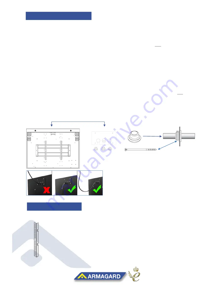
Check all apparatus for the installation is correct (Figure2) 

LCD MOUNTING 
BRACKET X2 

Figure 2 

(NOTE: Screws not provided 

– depends on display type) 4-6 needed, customer supplied 


STEP 

1

:


Unlock the door and position the enclosure on its back, securing the door stays within the 
side pins. 

STEP 

2

:


Choose the location you want to place your media player by taking into account the size 
of your display and the available space needed. Then secure just the cables from your 
media player and display into the mains surge protector.


STEP 

3

:


Carefully raise the enclosure up (Figure1) and feed the surge protectors main power 
cable out through the gland plate at the back of the unit (remove plate if necessary).


STEP 

4

:


Use either an open or closed grommet to fill the gland plate holes, while using cable ties 
to secure any open grommets until 

they’re water tight and screw the gland plate back if 

necessary (Figure1). 

NOTE:

  Make sure any cables fed through the gland plate come from below, and do not come 

down into the enclosure from above. Cables from above allow liquids to track this path into 
the unit (Figure1.5). 

STEP 

5

:


Close and lock the enclosure, then proceed to make up the plug for the enclosures 
main’s extension. 


Figure 1.5 

Grommets 

(Gland Plate) 

GLAND PLATE & CABLES 

DISPLAY BRACKETS 

Figure 1 

Содержание PDS 32

Страница 1: ...tions Tools required for installation Phillips Screwdriver Drill and Sockets Kit or Wrench READ THIS MANUAL THROUGH BEFORE INSTALLING YOUR UNITS TO ENSURE CORRECT INSTALLATION AND THAT YOU RE COVERED...

Страница 2: ...aling mount brackets LCD Mounting bracket x2 Reversible bracket x2 d parts Double ceiling bracket x 1 Single ceiling bracket x 1 1 PDS Enclosure x1 2 Keys x2 3 LCD Mounting Brackets x2 4 20mm Open Gro...

Страница 3: ...nd display into the mains surge protector STEP 3 Carefully raise the enclosure up Figure1 and feed the surge protectors main power cable out through the gland plate at the back of the unit remove plat...

Страница 4: ...halfway line of the unit STEP 10 Using the diagram shown in Figure4 fasten the brackets with the 4 or 6 screws suited to your LCD Display type Figure 3 Figure 4 STEP 9 For a balanced unit align the ce...

Страница 5: ...ir curtain and the enclosure window any less and you risk insufficient cooling to keep the display working Figure6 Figure 55 Figure 6 0 59 INCHES NOTE For screen adjustment continue to STEP 16 STEP 14...

Страница 6: ...g plate To Raise Loosen the screws and raise the interior bracket forwards and fasten to decrease the distance from the LCD screen and the window Figure9 To Lower Loosen the fittings rotate the bracke...

Страница 7: ...x2 Reversible bracket x2 Keys x4 Standard parts Double ceiling bracket x 1 Single ceiling bracket x 1 STEP 17 Once the LCD fits correctly remove the display set down in a safe area and then lock the e...

Страница 8: ...15 deg enclosure wall Bracket handed x2 Wall bracket x 1 Optional cealing mount brackets LCD Mounting bracket x2 Reversible bracket x2 Keys x4 ndard parts Double ceiling bracket x 1 Single ceiling bra...

Страница 9: ...sure brackets and wall plate are securely tightened steadily lift the enclosure onto the wall plate and secure ensuring the brackets are slotted over the wall plates top lip and the enclosure doesn t...

Страница 10: ...make sure it s correctly attached to the wall STEP 28 To fully secure the unit to the wall and prevent issues of theft take the locking bar and feed it through the slots on the mounting brackets and p...

Страница 11: ...ll use automatic thermostats instead Details on how to use the thermostat are found in the maintenance section Pg14 Kit Needed Armagard USB Cable Armagard USB Drivers Windows 7 Laptop Phillips Screwdr...

Страница 12: ...the terminal program mentioned from earlier and locate the setup port which will appear as a COM port Select the correct COM port from the drop down menu as shown in figure 3 box 1 The correct COM po...

Страница 13: ...omponents just above the menu shown in box 4 below Figure 4 10 The settings for each component can then be changed by selecting the appropriate option from the menu in box 5 For example to change the...

Страница 14: ...ling and 10 C 50 F for heating Simply turn the thermostat dial to the temperature you wish the component to turn on at it the fans are set to 40 C the fans will activate once the internal temperate re...

Страница 15: ...ther than those listed or any abrasive cleaners Avoid cleaners of a highly alkaline composition Avoid cleaning in the hot sun or high temperatures SCREEN CLEANING GLASS DISPLAY For high toughed glass...

Страница 16: ...46 47 52 55 www Armagard com Installation Manual Page 16 Toll Free US 1 866 434 0807 Call UK 0121 608 7210 For additional support visit www Armagard com or call Free US 1 866 434 0807 Call Free UK 012...

Отзывы: