Arkel ADrive 4B055 Скачать руководство пользователя страница 23

ARKEL Elektrik Elektronik Ltd. 

Ş

ti.                                                                                                                                    www.arkel.com.tr 

08.2012        


ADrive


22 

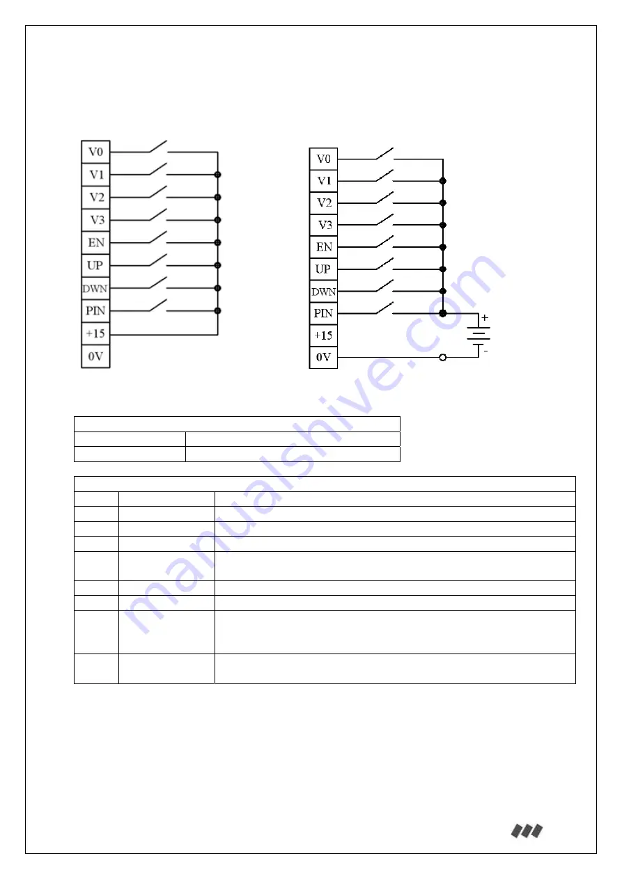
13.2. CONTROL TERMINAL CONNECTIONS 


13.2.1. Drive command inputs: 


Digital input specifications: 
Max. voltage 

26Vdc 

Clamping range 

Maks. 2,5 mm

2


Drive command input terminals: 

V0 Speed-0 

Low 

speed 

V1 Speed-1 

Inspection 

speed 

V2 

Speed 2 

Intermediate speed 

V3 Speed-3 

High 

speed 

EN 

ENABLE 

Drive enable (Must be switched by the open contacts of KPA and 
KPB main contactors) 

UP 

UP 

Travel direction up 

DWN  DOWN 

Travel direction down 

PIN Programmable 

input 

Programmable digital input. 
Can be assigned as “Error Reset”, “Check Fout<Flim”, “ApRe 
monitoring input” or “Brake monitoring input” in the menu. 

+15 +15V 

reference 

voltage 

Reference voltage for digital inputs (Imax: 100 mA) 


In a case of more than one speed inputs applied the higher one is activated. 


If the speed control inputs are driven by relay contacts, high speed and low speed signal should 
be applied together. Otherwise, because of the relay contact delay, wrong speed inputs may be 
perceived at speed changes especially for distance controlled stops it is important that there 
must be no delays at speed transitions. 


Re-levelling speed (VL) is active when V1 and V2 inputs are ON at the same time. V0 is don't 
care (X). V3 shall be OFF. 

a) Connection with internal power supply 

b) Connection with external power 

15Vdc, max. 100mA 
internal supply 

12-24Vdc,  
min. 100mA 
external supply 

Содержание ADrive 4B055

Страница 1: ...ADrive VVVF Inverter F Fo or r E El le ev va at to or rs s USER MANUAL 08 2012 Document Version 4 0 ...

Страница 2: ...nection for synchronous motors 30 13 2 5 Mechanical brake release monitoring 34 13 2 6 Motor brake resistor temperature monitoring 35 13 2 7 Manual evacuation mode activation input 35 13 2 8 External 24Vdc power supply 36 13 2 9 The connection between ENCABIT Plus module and ADrive 36 13 2 10 Inputs Outputs on ENCABIT Plus module 37 13 2 11 Serial communication with ARL 500 Lift Controller 38 13 2...

Страница 3: ...RY 62 6 CONTROL TYPE 62 7 LANGUAGE 62 8 FACTORY DEFAULT 62 9 AUTO TUNE 63 10 PASSWORD 63 11 ADVANCED SET 64 12 BATTERY OPERATION 67 13 DRIVE MODE 68 18 HOW TO ADJUST FOR OPEN LOOP PRACTICALLY 69 19 HOW TO ADJUST FOR CLOSED LOOP PRACTICALLY 70 20 DRIVING SYNCHRONOUS MACHINES with ADrive 71 21 TRIPS 74 22 NOTES 78 23 ADrive PARAMETER LIST 79 ...

Страница 4: ...tion connection control system operating starting service Disclaimer The containing information specifies the properties of the products without ensuring them The right for technical changes is reserved Copyright Copyright by Arkel Elektrik Elektronik Tic Ltd Sti It is not allowed to redistribute the manual in its entirety or parts of it Violations will be prosecuted and lead to indemnity ...

Страница 5: ... automatically readjusted and boring travels at low speed for short levels are impeded The parameter units are convenient for elevators m cm m s etc The mechanical fan noise and electrical switching noise are minimized by this no disturbing noises for residences close to machine rooms are produced 2 EMC CONFORMITY This product is in conformity with EN 61000 6 2 Generic standards immunity for indus...

Страница 6: ...d L3 are line input terminals and must not be disordered U V and W Otherwise device may be damaged Do not mount the brake resistor on controller cabinet Brake resistor must be mounted vertically outside the control cabinet Do not place device near flammable objects in order to prevent fire To prevent overheat damage and fire be sure that the environment has sufficient ventilation Do not store and ...

Страница 7: ...tation and software CD PC RS 232 connection cable Data Key for transferring parameters RFI Filter Zero phase reactor Braking resistor Optional EMI line filter Optional AC line reactor Optional ENCABIT Plus encoder interface module Required for synchronous drive ADrive Remote Keypad for remote operation of ADrive Optional ...

Страница 8: ...uts Absolute encoder simulation outputs Incremental encoder simulation outputs Protection Built in DC REACTOR Dc choke Input output isolation All isolated control inputs and outputs Cooling 4 low noise fans Serial communication ports RS 485 port for communication with lift controller CANbus port for communication with ENCABIT Plus Evacuation operation with back up power Control circuit supply With...

Страница 9: ...use Type B 1 5 x UPS_power W 220V Contactors Amper category AC 3 7 5HP 5 5kW 10HP 7 5kW 15HP 11kW 20HP 15kW 30HP 22kW 50HP 37kW Motor contactors KPA KPB 12 18 25 32 50 80 Mains supply contactor KSAK 9 12 18 25 40 65 Back up power supply contactor KKAK 9 9 12 18 32 50 Cable cross section mm 7 5HP 5 5kW 10HP 7 5kW 15HP 11kW 20HP 15kW 30HP 22kW 50HP 37kW Mains supply cables 2 5 4 6 10 16 Motor connec...

Страница 10: ...ooling air intake and discharge are not restricted in any way To ensure this allow a gap of at least 10 cm above and underneath the unit Mount using the mounting holes and using at most 12 mm M6 nuts 7 1 Physical Dimensions of ADrive Size B and Size C Dimensions mm ADrive Size B ADrive Size C W 260 289 H 387 442 D 184 205 H1 360 420 W1 230 5 250 5 A 30 B 24 C 8 E 18 F 8 G 8 H ADrive Size B 7 5HP 1...

Страница 11: ...d Şti www arkel com tr 08 2012 ADrive 10 7 2 Physical Dimensions of ADrive Size D Dimensions mm ADrive Size D W 350 H 590 D 236 5 H1 495 W1 316 A 30 B 24 C 8 E 18 F 8 G 8 I 95 J 80 K 80 L 95 ADrive Size D 50HP H W D W1 H1 I J K L ...

Страница 12: ...ing the device ADrive Size D follow the steps below Step 1 Screw one of the mounting devices and fastening brackets as shown in the figure Step 2 Screw the other mounting device to control panel as shown Step 3 Hang ADrive Size D to the mounting device on the control panel Step 4 Mount the device to control panel from two fastening brackets at the bottom of ADrive Size D Size D mounting device ...

Страница 13: ...osition But it is recommended to install the filter as load side comes close to ADrive input terminals 8 1 Dimensions of ADrive Line Filter ADrive Recommended EMI Filter Description Size B 7 5 HP 10 HP 15 HP EMC 30 3x400VAC 50 60HZ 30A Size C 20 HP 30 HP EMC 50 3x400VAC 50 60HZ 50A Size D 50 HP 3x400VAC 50 60HZ 80A Cable length 550 mm To ADrive input terminals L1 L2 L3 E From mains supply L1 L2 L3...

Страница 14: ...l position for best heat dissipation and must be fitted with its connecting bars Do not mount the braking resistor on the controller cabinet While mounting be aware that excessive heat dissipated by the brake resistor may damage the control panel cause malfunctions or start a fire The temperature of the break resistor housing can attain 100 C during operation The brake resistor must be mounted in ...

Страница 15: ...012 ADrive 14 9 1 Dimensions of Braking Resistors 9 1 1 Braking Resistor Type A 7 5 HP 10 HP 15 HP 9 1 2 Braking Resistor Type B 20 HP 30 HP 9 1 3 Braking Resistor Type C 50 HP 225 mm 20 mm 155 mm 305 mm 180 mm 325 mm 20 mm 115 mm 450 mm 320 mm 250 mm 20 mm ...

Страница 16: ...e wires two times to attain the full RFI filtering effect Install the toroidal core near the inverter as close as possible 10 2 The wiring of ADrive Size D RFI Filter The toroidal transformer core comes with the inverter is used for RFI filter The wiring must go through the opening U V W to reduce the RF component of the electrical noise Loop the wire one time to two toroid to attain the full RFI ...

Страница 17: ... 75 140 0 3 0 5 Note It is recommended to use AC line reactors with impedance values 3 Z for standard applications The impedance value Z is also the voltage value that drops across the AC line reactor for example 5 voltage drops across the AC line reactor with impedance value 5 5 reactor would be a better choice for reducing the harmonic currents with a balanced mains supply less than 5 voltage im...

Страница 18: ...ous motors are provided with the support of ENCABIT Plus module 12 2 Mounting ENCABIT Plus module is installed to the bottom right of ADrive as ENCABIT Plus mounting ears comes to the appropriate slots on ADrive Dimensions mm Height 173 Width 108 Depth 35 ENCABIT Plus module fastening hole with M4x8 screw ENCABIT Plus module mounting holes Assembly of ENCABIT Plus module to ADrive ENCABIT Plus mod...

Страница 19: ...rive Connections 13 1 Connections of ADrive Size B and Size C Bottom view of ADrive Inverter 13 2 Connections of ADrive Size D Bottom view of ADrive Inverter Line Inputs Motor Output Control Terminal Inputs FAN GROUP Control Terminal Inputs Line Inputs Motor Output FAN GROUP ...

Страница 20: ...negative voltage This terminal is located in only ADrive Size B and Size C U Motor outputs V W 13 1 1 Mains power connection Use a cable with an appropriate cross section For more information see section 6 13 1 2 Brake resistor connection Use a shielded cable with an appropriate cross section For more information see section 6 3 Phase AC Mains Supply 340V 420V PE 50 60Hz L1 R L2 S L3 T PE 3 pole T...

Страница 21: ...ARKEL Elektrik Elektronik Ltd Şti www arkel com tr 08 2012 ADrive 20 13 1 3 Motor connection 13 1 3 1 Asynchronous motor connection 13 1 3 2 Synchronous motor connection ADrive Motor ADrive Motor ...

Страница 22: ...ue to the high current main contacts MUST be used for short circuiting For synchronous drive the drive enable signal EN must also be switched by a NO contact of an auxiliary relay The auxiliary relay has to be connected parallel to the travel contactors See section 13 2 1 1 The length of the motor wire should not be longer than 10 meters If the motor wire need to be longer than 10 meters a motor o...

Страница 23: ... ApRe monitoring input or Brake monitoring input in the menu 15 15V reference voltage Reference voltage for digital inputs Imax 100 mA In a case of more than one speed inputs applied the higher one is activated If the speed control inputs are driven by relay contacts high speed and low speed signal should be applied together Otherwise because of the relay contact delay wrong speed inputs may be pe...

Страница 24: ...n will be delayed and the motor circuit will be opened by the main contactors while the device is still continue to driving This situation may cause excessive current draw from the device Driver will give IPM error in these cases Therefore to avoid this situation that shorten the life time of the device it is recommended to switch the drive enable signal EN also from a NO contact of an auxiliary r...

Страница 25: ...A RHA Error relay NO contact RHO Error relay COM contact RPA Driver running relay NO contact Driver running signal output This output should be used when the lift controller releases the main contactors with a release command coming from the inverter The relay remains activated during the drive RPO Driver running relay COM contact RFA Mechanical brake relay NO contact Mechanical brake contactor ou...

Страница 26: ...e contactor must be used to disconnect the AC supply Disconnecting the DC supply directly while AC supply is still connected will cause arcs on the contact plates and will shorten the lifetime of the contacts For that reason the contacts on DC circuit must only be opened after the AC supply is cut off This will ensure that the contacts will only be used to disconnect the mechanical brake supply on...

Страница 27: ...d as common GND of additional transistor outputs 13 2 2 3 Additional digital inputs Additional input terminals CI1 Additional input 1 Activation input for battery operation When 24Vdc is applied to this input inverter goes into battery operation mode This input must not be activated when the 3 phase AC supply is connected to inverter For more information about battery operated evacuation see secti...

Страница 28: ...and switch off the inverter Use a shielded cable for connection Do not ground the encoder through both the motor and inverter If the encoder is isolated from the motor and from ground then connect the cable shield to the inverter housing Motor cable and encoder cable channels should be separate Minimum distance between cables should be at least 10cm To minimize the distortion cable lengths should ...

Страница 29: ... are shown Please contact authorized seller for different types of encoder Also the electrical diagram of encoder input circuit will help to arrange different types of encoder OA OB A A B B JP 15 _ _ 5 0V 5V TTL ENCODER OA OB A A B B JP 15 _ _ 5 0V 12 24V HTL ENCODER WITH COMPLEMENTAL OUTPUTS WITH COMPLEMENTAL OUTPUTS OA OB A A B B JP 15 _ _ 5 0V 12 24V HTL ENCODER WITH SINGLE OUTPUTS ...

Страница 30: ...put circuit X1 A R17 330 R16 330 X4 A 10nF C4 R25 680 14 8 9 3 12 U1C LM339N X6 B R15 330 R14 330 X5 B 10nF C3 R23 680 2 4 5 3 12 U1A LM339N BCO ACO IO 15V IO 15V IO GND IO GND R18 1K R19 1K 10uF 16V C5 X2 JP IO 15V IO GND ACO BCO IO 15V IO 15V JP X2 OA X3 OB X7 R76 3K9 R26 100R R77 3K9 R27 100R 1 6 7 3 12 U1B LM339N 13 11 10 3 12 U1D LM339N IO 15V IO GND IO 15V IO GND ...

Страница 31: ...mware update must be performed 13 2 4 1 Encoder connection with X ENC1 connector for EnDat and SSI encoders This connection method is suggested when the encoder connection cable has a ready made 15 pole SUB D connector on driver side end and the pin configuration of the SUB D connector corresponds to ENCABIT Plus module The pin assignment of X ENC1 connector is shown in the table below X ENC1 conn...

Страница 32: ...ncoder SinCos encoder A A A A A A B B B B B B DA Data DA Data CL Clock CL Clock D D D D C C C C 5V 5V Up 5V Sensor 5V Up 5V Sensor 0V 0V Un 0V Sensor 0V Un 0V Sensor It is recommended to connect the encoder wires 5V Sensor and 0V sensor in parallel to terminals 5V Up and 0V Un There is no terminal on the encoder terminal group to earth the encoder cable screen If earthing the cable screen is neede...

Страница 33: ... shield to the grounding conductor on the inverter When connecting the encoder cable with SUB D connector please ensure that the pin configuration of the encoder cable corresponds to the pin configuration of the ENCABIT Plus module Faulty connection may cause un repairable damage to the encoder or the inverter The connection cable of encoder may never be unplugged or removed under voltage Make sur...

Страница 34: ...ase B 24V The resolution of the encoder simulation outputs is identical with the encoder resolution Use a shielded twisted pair cable for connection Connect the cable shield to the inverter housing To minimize the distortion cable lengths should be as short as possible Encoder simulation cable channel should be separated from motor and other power cables Minimum distance between cables should be a...

Страница 35: ...nd must be connected in serial When brakes are closed this input must be ON The microswitches of the brakes can be connected either to input PI1 on ENCABIT Plus module or programmable input PIN on ADrive To activate the self monitoring function of the brakes parameter 11 6 Brake mon must be enabled This parameter is set to Disabled in factory settings It shall be enabled only after wiring the brak...

Страница 36: ...manual evacuation mode screen The direction of car The speed of car Over speed warning The evacuation speed must not exceed 0 63 m s SPEED 0 4 m s DIR When the manual evacuation mode is activated the speed m s is shown on the top line and the direction or is shown on the bottom line of the evacuation screen SPEED 0 65 m s STOP V 0 63 When the evacuation speed exceeds 0 63 m s a warning message wil...

Страница 37: ...Drive inverter o Drive command inputs and relay outputs o Incremental encoder inputs and simulation outputs o RS 485 serial communication protocol communication with ADrive Remote Keypad or ARL 500 lift controller o CANbus connection with ENCABIT Plus module On ENCABIT Plus module o Digital inputs and transistor outputs o Absolute encoder inputs and simulation outputs 13 2 9 The connection between...

Страница 38: ...stor temperature monitoring Can be activated in the menu PI3 Input 3 Manual evacuation mode activation input PI4 Input 4 Reserved input PI5 Input 5 Reserved input 24V 24Vdc reference voltage Reference voltage for digital inputs 24V 13 2 10 2 ENCABIT Plus transistor outputs ENCABIT Plus transistor output terminals PO1 Transistor output 1 Reserved output PO2 Transistor output 2 Reserved output GND O...

Страница 39: ...is made Speed inputs V0 V1 V2 V3 Direction inputs UP DWN Error output RHO RHA Driver running output RPO RPA Encoder simulation outputs ADrive remote keypad connection 13 2 12 ADrive Remote Keypad Connection ADrive Remote Keypad is an external remote control terminal used when direct access to ADrive control panel is not possible All adjustments can be made remotely from the keypad panel The connec...

Страница 40: ...e the lower load direction or command direction given by the lift controller If the evacuation operation is performed in the lower load direction 60Vdc battery back up supply will be sufficient If the evacuation operation is performed in the command direction given by the lift controller not in the lower load direction because the required power for moving the car is increased a battery pack with ...

Страница 41: ...ightly 13 3 3 1 Back up Power Requirement Calculations for Evacuation Towards Lower Load Direction As the car will be moved in the same direction in which the gravity forces the system to move the back up power will only be used to slow down the car and if the system is nearly balanced to accelerate the car If the travel speed on evacuation is set too low this will elongate the travel time and wil...

Страница 42: ...tion Towards Command Direction On Evacuation Towards Commanded Direction the worst case scenarios are when the command is up with a fully loaded car or when the command is down with an empty car Therefore auxiliary power requirement calculations must be made considering these scenarios Using a low speed setting for evacuation will reduce instantaneous power requirements but will increase evacuatio...

Страница 43: ...ower is supplied to the real system Car is unloaded Evacuation speed limit is set by the 12 3 BAT Speed parameter recommended to set it to 1 4th of nominal speed The current drawn from mains during evacuation in downwards direction is measured Minimum required power W 220 V x Measured current A Minimum required power VA 220 V x Measured current A x 1 4 The UPS should be chosen such that its power ...

Страница 44: ...nals L1 and L3 Do not make different connection Otherwise the device may be damaged FM Mains fuse LF Line filter BAT Batteries UPS 1 phase 220Vac uninterruptible power supply LCS Lift control system FAKU Battery fuse KSAK Mains supply contactor KKAK Battery supply contactor 1 Contactor KSAK and KKAK must be interlocked 2 Activation of for battery operation CI1 input See Section 6 for appropriate f...

Страница 45: ...use LF Line filter UPS 1 phase 220Vac uninterruptible power supply LCS Lift control system FUPS UPS fuse KSAK Mains supply contactor KKAK Battery supply contactor 1 Contactor KSAK and KKAK must be interlocked 2 Activation of for battery operation CI1 input See Section 6 for appropriate fuse contactor and cable cross section 1 LCS ADrive UPS 2 LCS 24V 24V FUPS ...

Страница 46: ...rive ENABLE signal input terminal EN by activating the main contactors KPA and KPB Control applies the speed and direction command to the inverter If the parameter 12 2 DIRECTION is set as BD EASIEST DIR Inverter ignores the applied speed and direction commands and starts running the motor in the optimum direction easy direction with a maximum speed limited with V4 speed If the parameter 12 2 DIRE...

Страница 47: ...are By this way new features facilities can be added to the product ARKEL Firmware Updater is an utility software which connects your computer and the device enabling you to load the firmware file to your device The device firmware file is not a part of this software The latest firmware file which is compatible with device can be downloaded from our web site Before downloading firmware you must le...

Страница 48: ...hich is memory device and comes with ADrive can save parameters from the ADrive Inverter or can transfer the parameters inside to the ADrive Inverter The plug on ADrive which is used for Data Key connection is 9 pin D type male Do not use this plug for PC connection ADrive Data Key plug Data Key ...

Страница 49: ...ve user panel ADrive has an LCD screen with 2 row 16 character and 5 key keypad These buttons function as follows Enter menu submenu Select parameter edit value Exit menu submenu To next previous monitoring screen To next previous parameter Increase decrease parameter value Change digit of parameter value ...

Страница 50: ...URE 0 MOTOR TEMPERATURE SCREEN Approximate motor temperature is displayed on this screen RPM 0 RPM ERROR SCREEN CLOSED LOOP Rpm error is displayed on this screen This error is the difference between the inverter operation value and the encoder value sign indicates this difference by moving left right If sign is at the right side of display it means motor is running faster than inverter operates If...

Страница 51: ...f CANbus serial communication between ENCABIT Plus module and ADrive RS485 The number of packets per second of RS 485 serial communication with ADrive Remote Keypad or lift controllers Vref 1 20 m s Vact 1 19 m s SPEED MONITORING SCREEN Vref Reference target speed Vact Actual current speed Encabit PI 01000 Enc_pos 001A3f22 ENCABIT Plus MONITORING SCREEN Encabit PI The state of the 5 digital inputs...

Страница 52: ... or by a PC or Laptop on which ADrive Win software is installed Parameters are grouped according to their functions The parameters and functions according to groups are explained below 1 TRAVEL CURVE 2 MOTOR SETUP 3 CONTROLLER SETUP 4 KEY READ WRITE 5 FAULT HISTORY 6 CONTROL TYPE 7 LANGUAGE 8 FACTORY DEFAULT 9 AUTO TUNE 10 PASSWORD 11 ADVANCED SET 12 BATTERY OPERATION 13 DRIVE MODE ...

Страница 53: ...N 1 6 ACCELERATION BEGIN SOFTEN S1 1 7 ACCELERATION END SOFTEN S2 1 8 SLOWING DISTANCE 1 9 STOPPING DISTANCE 1 10 STOPPING TYPE 1 11 DECELERATION 1 12 DECELERATION BEGIN SOFTEN S3 1 13 DECELERATION END SOFTEN S4 1 14 MECHANICAL BRAKE ON DELAY 1 15 MECHANICAL BRAKE OFF DELAY 1 16 INITIALIZING JERK 1 17 INITIALIZING SPEED 1 18 INITIALIZING TIME 1 20 RE LEVELLING SPEED ...

Страница 54: ...ased smoothly to prevent sharp changes in the acceleration Consequently the acceleration is felt less by the passenger 1 8 Slowing Distance X_SLW 10 500 cm If the STOPPING TYPE at Parameter 1 10 is adjusted to STP WITH DISTANCE while the elevator speeds down from V3 to V0 the distance to slow down from V3 to V0 is equalized to the value of this parameter automatically by adjusting the S ramps No n...

Страница 55: ...uses the motor power cut off before the mechanical brake blocks motor In this situation the car may move out of control to heavier direction The elevator controller card must hold the contactors till the end of the this time If this is not done the sparks at contactor contacts may disturb the driver 1 16 Initializing Jerk As 0 01 4 00 m s Instead of starting directly with the S ramp the elevator m...

Страница 56: ...uency 2 8 Motor power factor COS Q 2 9 Rotor slip 2 10 No load motor current 2 11 Rotor time constant 2 12 Middle frequency 2 13 Middle frequency voltage 2 14 Minimum frequency 2 15 Minimum frequency voltage 2 16 Thermal mod 2 17 Motor direction 2 18 Encoder direction 2 19 Number of poles 2 20 Encoder offset 2 21 Absolute encoder type Motor setup affects the driver s performance directly so these ...

Страница 57: ...io 1 60 and rope suspension ratio 1 1 s m Vnom 1 1 60 60 1430 4 0 2 2 2 Motor RPM At Nominal Speed Rpm_Motor 100 5000 rpm The motor RPM at which nominal speed is gained 2 3 Incremental Encoder Resolution Pulse 100 5000 Pulse Rev The pulse of the incremental encoder per revolution This parameter is not used for absolute value encoders 2 4 Line Voltage Vline 300 420 Volt Line voltage applied to L1 L...

Страница 58: ...or example The slip for a 50Hz 1440 rpm 4 poles motor is like below 1500 2 60 50 pm StatorNomR Rpm 2 50 1500 1440 1500 Fslip Hz 2 10 No Load Motor Current Inoload 20 80 Ratio of no load current to nominal current Too high value causes high motor current Consequently motor heat rises and more power consumed Too low value causes torque loss which shows itself as a vibration Values of parameters 2 9 ...

Страница 59: ...ues increases thermal protection sensitivity 2 17 Motor Direction Not inverted Inverted This parameter can be used to change the motor direction If motor goes in the wrong direction the wires to the motor must be reversed Motor s direction can also be reversed easily by using this parameter without making any wiring changes 2 18 Encoder Direction Not inverted Inverted This parameter can be used to...

Страница 60: ...hronous Machines with ADrive After the auto tune process note the value of this parameter When the inverter need to be changed because of a failure this parameter must be set to this value manually for the new inverter without performing a new auto tune process The auto tune process must be performed when the relative position between motor and encoder changes 2 21 Absolute encoder type SC EnDat 2...

Страница 61: ...peed step by step At start up of elevator KI0 and KP0 is hold high to make the PI speed controller s reaction faster to very little speed changes At full speed there is no need for so much sensitive PI controller because it causes high motor enforce For example at start up the reaction must be quick to 5 10 revolution changes while at 1400 rpm it is meaningless to give sudden torque changes for 5 ...

Страница 62: ...more quick response to rollback Reducing the gains will cause late response Too high gain values can lead noisy and instable start up Too low gain values cause an appreciable rollback in car See section 20 4 Improving start ups for appropriate Anti Rollback settings 3 6 Anti Rollback position controller Kp gain KP_ARB 10 2000 The Kp gain of Anti rollback position controller 3 7 Anti Rollback posit...

Страница 63: ...the screen Last error is number 1 and the oldest error is number 256 5 2 Clear Fault List All faults in the memory are erased 6 CONTROL TYPE Determines that if the control of the motor will be in OPEN LOOP without encoder mode or in CLOSED LOOP with encoder 6 1 Control Type CT OPEN LOOP CLOSED LOOP When synchronous motor is selected in the menu this parameter can be adjusted only as a closed loop ...

Страница 64: ...performed when the motor is free from any load or when the car and counter weight are in exact balance During auto tuning the motor will turn 1 revolution clockwise and 1 revolution counter clockwise For static auto tuning this parameter must be set to ENABLE_STATIC Statc auto tuning is performed while the mechanical brakes are locked and the motor is under load Therefore the motor will not move d...

Страница 65: ...10 1000 The current controller KI gain Default setting is 75 11 3 The current controller KP gain KP cur 1000 30000 The current controller KP gain Default setting is 4000 11 4 PIN programmable input function Error Reset Check Fout Flim APRE mon input Brake mon input This parameter determines the function of digital programmable input PIN on ADrive Error reset The device error will be cleared by act...

Страница 66: ...Test Instructions for further information 11 7 PTC temperature monitoring Enabled Disabled The control of PTC temperature monitoring function Motor PTC brake resistor thermostat can be connected to PI2 input on ENCABIT Plus module usually when the inverter and the lift controller are located in separate places In order to enable this function the driver must be equipped with ENCABIT Plus module an...

Страница 67: ... enable the rotor to stand still without rolling back That s why PI controller gains for the motor current 11 2 KI_cur and 11 3 KP_cur are desired to be as high as possible during startup But adversely keeping these gains high during travel will cause fluctuations in motor current and will cause vibrations and humming noises This parameter allows reducing the gains during travel For example if thi...

Страница 68: ...ng the motor in the direction applied to input terminals UP DWN with a maximum allowed speed limited with the parameter 12 3 12 3 Battery speed V4 0 05 5 00 m s Maximum evacuation speed allowed during evacuation operation The maximum speed that can be achieved during evacuation operation depends on the type of motor and loading of the car evacuation in the lower load evacuation or command directio...

Страница 69: ...auses max acceleration in the elevator The max current value can be applied to the motor in this mode is the value set by parameter 11 13 current limit In addition over speed low speed motor overload and ApRe monitoring error detection are disabled Refer to ADrive A3 Test Instructions for further information Safety Gear Unjamming Safety gear unjamming mode This function is only available for firmw...

Страница 70: ... change these parameters to speed up or slow down the elevator These parameters are only machine information Enter the speed references at TRAVEL CURVE menu For applications to speed up the elevator over the nominal speed adjust the high speed maximum 30 over the nominal speed For example nominal speed 0 6m sn maximum high speed 0 8 m sn or nominal speed 1 m sn maximum high speed 1 3 m sn Be sure ...

Страница 71: ...z to 3 0Hz with 0 3Hz steps and make a test run with same way same load The appropriate slip value is the one which your motor current is lowest Note If the motor does not reach the estimated rpm it means that the motor slip is low If motor current is not stable and there is a high oscillation it means that the motor slip is high If you cannot solve the vibration problem To find the source of prob...

Страница 72: ...ed by manually releasing the brakes and making sure that the car does not move with released brakes During dynamic autotuning the motor will turn one revolution in each direction So please make sure that the car has enough distance to the top and bottom of the shaft before starting the autotuning In cases where dynamic auto tuning is not possible auto tuning may be performed statically For static ...

Страница 73: ...e shaft This is the situation with the worst case of weight balance c Set the 3 5 AntiRollBack parameter to Enabled d Set the 3 6 KP_ARB parameter to 60 Set the 3 7 KD_ARB parameter to 20 Press the down button in the recall terminal The car will slip upwards a little and will stop After the end of Mechanical brake opening time which we had set to 2 seconds the car will start to move downwards with...

Страница 74: ...and 3 4 KI1 to 10 3 9 Encoder filter to 2 b By pressing the up button on ADrive keyboard find the RPM Error Screen Give a command to the elevator and observe the rpm error while the car is accelerating and decelerating If the rpm error goes beyond 5 increase the KI and KP gain coefficients As the gain coefficients are increased the controller will respond more quickly to the difference between the...

Страница 75: ...s 200V 1 If mains power is active The main supply voltage may be too low Check the L1 L2 L3 voltages 2 If battery power is active Check the battery voltage on the terminals L1 and L3 03 HIGH DC BUS The DC Bus voltage exceeded the overvoltage detection level If mains power is active Vbus 715 V If UPS power is active Vbus 420V 1 Braking resistor may not be connected properly Check broken or disconne...

Страница 76: ...elded use a shielded cable 4 If the motor cable is not shielded use a shielded cable 5 Encoder cable may be placed too close to motor cable Motor cable and encoder cable channels should be separate Minimum distance between cables should be at least 10cm 6 Encoder may be grounded at both the motor side and inverter side If the encoder is grounded at motor side disconnect the grounding at inverter s...

Страница 77: ... outputs 1 Ensure that the main contactors are not picked up and dropped out during the drive 2 Check the connection of ENABLE signal 3 Check whether there is a looseness in motor and contactor connection 4 Ensure that the components such as brake coil contactor coil that may create electrical noise have appropriate filtering 22 Fout Flim Drive output frequency is higher than the limit value set i...

Страница 78: ...e sure that the braking resistor is suitable for Inverter s power and motor power 31 LOW CPU SUPPLY The CPU supply is low Only in ADrive Size D 1 The value of 3 phase AC supply may have fallen below 340 V Check the voltage of the terminals in L1 L2 and L3 2 If the device is being supplied from an external 24 VDC source check the voltage of this external source 3 If the circuit voltages are all nor...

Страница 79: ...ARKEL Elektrik Elektronik Ltd Şti www arkel com tr 08 2012 ADrive 78 22 NOTES ...

Страница 80: ...tor nominal frequency 50 Hz 2 8 Motor power factor COS Q 0 8 2 9 Rotor slip 2 0 Hz 1 7 Hz 1 5 Hz 1 2 Hz 1 Hz 0 7 Hz 2 10 No load motor current 40 2 11 Rotor time constant 150 ms 150 ms 250 ms 300 ms 400 ms 500 ms 2 12 Middle frequency 4 0 Hz 2 13 Middle frequency voltage 40 V 2 14 Minimum frequency 0 5 Hz 2 15 Minimum frequency voltage 22 V 2 16 Thermal mod 100 2 17 Motor direction Not inverted 2 ...

Страница 81: ...TINGS FACTORY DEFAULTS Induction Synchronous 5 5 kW 7 5 kW 11kW 15kW 22kW 37kW 5 5 kW 7 5 kW 11kW 15kW 22kW 37kW 12 BATTERY OPERATION 12 1 Battery voltage 220 UPS 12 2 Battery direction Easiest direction 12 3 Battery speed 0 1 m s 12 4 UPS power 20 0 kW 13 DRIVE MODE 13 1 Drive mode Normal ...

Страница 82: ...ww arkel com tr 08 2012 ADrive 81 ARKEL Elektrik Elektronik Ticaret Ltd Şti Şerifali Mah Bayraktar Bulvarı Şehit Sok No 32 Ümraniye İstanbul TÜRKİYE Tel 90 216 540 03 10 pbx Fax 90 216 540 03 09 E mail info arkel com tr www arkel com tr ...

Отзывы: