AZI Sales/Customer Service 800-528-7411 or 602-470-1414 or [email protected]
Page 64 of 105
Before performing Temperature Calibration:
•
Navigate
[MENU]
SETUP MENU
PRINTER SETUP.
•
Verify that OUTPUT TO COMPUTER is set to
No
. Change it to
No
if necessary.
•
Press
[ESC]
until back at the Main Menu.
Since the TCI port can also be used to output data to a computer, in order to ensure
communication between the instrument and the TCI, data output through this port must
be turned off during temperature calibration. If you typically output data from the
instrument to a PC, be sure to re-enable this function when temperature calibration is
complete. See
Connecting the Temperature Calibration Kit:
•
Open the lid.
•
Use the supplied tweezers to remove the pan support; place the tweezers’ tips under
the pan support and pry the pan support straight up and out of the balance stem.
Be
careful; excess force on the balance can result in costly repairs.
•
Set the pan support aside during the calibration.
•
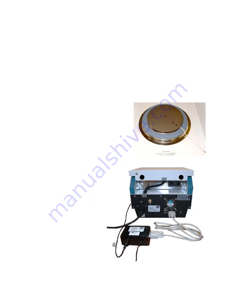
Place the RTD calibration disk onto the top of
the balance cover so that the disk support sinks
into the center hole of the balance cover.
•
Turn the RTD calibration disk so that the wires
are positioned at the 4:30 clock position, when
facing the instrument from the front, as shown.
•
Plug the RTD calibration disk cable into the
matching connector on the Temperature
Calibration Interface (TCI) Module, as shown.
•
Connect the RS-232
serial cable to the
matching connector on
the TCI module and to
the “TCI” port on the
back of the instrument,
as shown.
•
Connect the 9VDC
adapter to the TCI
Module and to an
appropriate AC outlet, as
shown.
•
After calibration, be sure
to disconnect the TCI
from the TCI port on the
instrument prior to
printing any reports.
To AC
Power
Adapter
To AC
Power


