background image

48

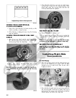
Inspecting Camshaft 
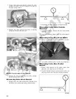
Spring/Unloader Pin 

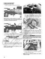
1. Inspect the spring and unloader pin for damage.

CF061A

NOTE: With the weight extended, the unloader pin

should be flat-side out; with the weight retracted, the
unloader pin should be round-side out.

CF060A

2. If damaged, the camshaft must be replaced.

Installing Top-Side 

Components

A. Piston
B. Cylinder

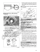
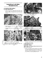
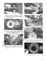
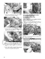
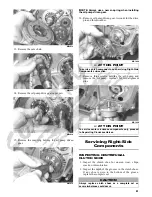
1. Lubricate the piston pin, connecting rod, and piston

pin bore with motor oil; then install the piston on the

connecting rod making sure there is a circlip on each

side.

NOTE: The piston should be installed so the IN

points towards the intake.

FI626

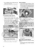
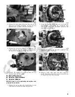
2. Place the two alignment pins into position. Place a

new cylinder gasket into position; then place a piston

holder (or suitable substitute) beneath the piston skirt

and square the piston in respect to the crankcase.

MD1344

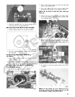
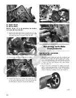
3. Lubricate the inside wall of the cylinder; then using a

ring compressor or the fingers, compress the rings

and slide the cylinder over the piston. Route the cam

chain up through the cylinder cam chain housing;

then remove the piston holder and seat the cylinder

firmly on the crankcase.

 GZ142

 4. Loosely install the two nuts securing the cylinder to

the right-side crankcase half.

NOTE: The two cylinder-to-crankcase nuts will be

tightened in step 9.

CAUTION

The cylinder should slide on easily. Do not force the cyl-
inder or damage to the piston, rings, cylinder, or crank-
shaft assembly may occur.

Содержание 2014 XC 450

Страница 1: ...450 ATV SERVICE MANUAL 2014 ...

Страница 2: ... decals display the words Warning Caution Note and At This Point to emphasize important information The symbol WARNING identifies personal safety related information Be sure to follow the directive because it deals with the possibility of serious injury or even death A CAUTION identifies unsafe practices which may result in ATV related damage Follow the directive because it deals with the possibil...

Страница 3: ......

Страница 4: ...ling Left Side Components 57 Right Side Components 58 Removing Right Side Components 58 Servicing Right Side Components 61 Installing Right Side Components 62 Center Crankcase Components 65 Separating Crankcase Halves 65 Disassembling Crankcase Half 66 Servicing Center Crankcase Components 67 Assembling Crankcase Half 72 Joining Crankcase Halves 74 Installing Engine Transmission 75 Fuel Lubricatio...

Страница 5: ...cting Rod big end width 21 95 22 00 mm Connecting Rod small end deflection max 3 0 mm Crankshaft web to web 60 9 mm Crankshaft Runout max 0 03 mm CYLINDER PISTON AND RINGS Piston Skirt Cylinder Clearance 0 025 0 055 mm Piston Diameter 8 mm from Skirt End 88 96 88 98 mm Piston Ring Free End Gap max 1st 2nd 11 6 mm 10 1 mm Bore x Stroke 89 0 x 71 2 mm Cylinder Trueness max 0 01 mm Piston Ring End Ga...

Страница 6: ...ine 20 27 Rear Drive Input Shaft Housing Differential Housing 23 31 Lock Collar Differential Housing 125 169 Wheel Steel Hub 40 54 Wheel Aluminum Hub 80 108 Rear Drive Gear Case Frame 38 52 Engine Output Flange Rear Gear Case Input Flange 20 27 ENGINE TRANSMISSION Part Part Bolted To Torque ft lb N m Clutch Shoe Crankshaft 147 199 Clutch Cover Housing Assembly Crankcase 8 11 Left Side Cover Crankc...

Страница 7: ...anol or 5 methane are acceptable gasolines When using ethanol blended gasoline it is not necessary to add a gasoline antifreeze since ethanol will prevent the accumulation of moisture in the fuel system RECOMMENDED ENGINE TRANSMISSION OIL The recommended oil to use is Arctic Cat ACX All Weather synthetic engine oil which has been specifically formulated for use in this Arctic Cat engine Although A...

Страница 8: ...pidly inject the preserver into the air filter opening for a period of 10 to 20 seconds Stop the engine Install the air filter and housing cover 4 Plug the exhaust outlet on the muffler with a clean cloth 5 Apply light oil to the upper steering post bushing and plungers of the shock absorbers 6 Tighten all nuts bolts cap screws and screws Make sure rivets holding components together are tight Repl...

Страница 9: ...ary 5 Charge the battery then install Connect the battery cables 6 Check the entire brake systems fluid level pads etc all controls lights and headlight aim adjust or replace as necessary 7 Tighten all nuts bolts cap screws and screws mak ing sure all calibrated nuts cap screws and bolts are tightened to specifications 8 Check tire pressure Inflate to recommended pressure as necessary 9 Make sure ...

Страница 10: ...uster 0444 178 Item Initial Service After Break In First Mo or 100 Mi Every Day EveryMonthor 100 Miles Every 3 Months or 300 Miles Every 6 Months or 500 Miles Every Year or 1500 Miles As Needed Battery I I C Fuses I R Air Filter Drain Tube I I C R Valve Tappet Clearance I I A Engine Compression I Spark Plug I I R 4000 Mi or 18 Mo Muffler Spark Arrester C R Gas Hoses I I R 2 Yrs Throttle Cable I I ...

Страница 11: ...leaning solvent then dip the ele ment in the solvent and wash it NOTE Foam Air Filter Cleaner and Foam Air Filter Oil are available from Arctic Cat 4 Dry the element 5 Put the element in a plastic bag then pour in air filter oil and work the oil into the element Insert the form ing spring into the element with the closely wrapped end of the spring toward the open end of the element 6 Clean any dir...

Страница 12: ...mission Ser vicing Top Side Components CF005 2 Rotate the crankshaft to the TDC position on the compression stroke NOTE At this point the rocker arms and adjuster screws must not have pressure on them Feeler Gauge Procedure Using a feeler gauge check each valve tappet clearance If clearance is not within specifications loosen the jam nut and rotate the tappet adjuster screw until the clear ance is...

Страница 13: ...ir blow any debris from around the spark plug 3 Remove the spark plug then attach the high tension lead to the plug and ground the plug on the cylinder head well away from the spark plug hole 4 Attach the Compression Tester Kit NOTE The engine must be warm and the battery must be fully charged for this test 5 While holding the throttle lever in the full open posi tion crank the engine over with th...

Страница 14: ...r conditions of the area in accordance with the coolant manufacturer s recommendations While the cooling sys tem is being filled air pockets may develop therefore run the engine for five minutes after the initial fill shut the engine off and then fill the cooling system to the bot tom of the stand pipe in the radiator neck Checking Filling 1 Locate the coolant reservoir on the right side behind th...

Страница 15: ...e on this model Engine Transmission Oil Filter The engine should always be warm when the oil is changed so the oil will drain easily and completely 1 Park the ATV on level ground 2 Remove the seat and left side engine cover 3 Remove the oil level stick filler plug FI530C 4 Remove the drain plug from the bottom of the engine and drain the oil into a drain pan 733 441A 5 Remove the oil filter plug f...

Страница 16: ... the threads of the plug If low add SAE approved 80W 90 hypoid gear lubricant as necessary To change the lubricant use the following procedure 1 Place the ATV on level ground then remove each fill plug KC0077A 2 Drain the lubricant into a drain pan by removing the drain plug from each ATV0082A 737 651B 3 After all the oil has been drained install the drain plugs and tighten to 45 in lb 4 Pour the ...

Страница 17: ...sing the Tachometer start the engine and run at 1500 RPM ignition timing should be 10 BTDC 3 Install the timing inspection plug If ignition timing cannot be verified the rotor may be damaged the key may be sheared the trigger coil bracket may be bent or damaged or the ECM may be faulty Lights Rotate the ignition switch to the lights position the head lights and taillights should illuminate Test th...

Страница 18: ...kwise and remove from the housing KC157 2 Press in and turn the bulb counterclockwise to remove Press in and turn clockwise to install the bulb 3 Insert the bulb socket assembly into the housing and turn it clockwise to secure RUNNING LIGHTS BACK UP LIGHTS The running lights are located outboard of the headlights and the back up lights are outboard of the tail lights brakelights To replace the bul...

Страница 19: ...counterclockwise to lower the beam KC406A Shift Lever CHECKING ADJUSTMENT KC165 With the engine stopped and the brake lever lock engaged turn the ignition switch to the ON position then shift the transmission into each of the gear positions and note that the gear position indicated on the LCD corre sponds to the gear position selected by the lever If the indicator does not correspond to the select...

Страница 20: ...ke is not firm the system must be bled 3 To bleed the brake system use the following proce dure A Remove the cover and fill the reservoir with DOT 4 Brake Fluid B Install and secure the cover then slowly compress the brake lever pedal several times C Remove the protective cap install one end of a clear hose onto one REAR bleeder screw and direct the other end into a container then while holding sl...

Страница 21: ...o 20 ft lb PR377B 5 Install the wheel Tighten to 40 ft lb steel or 80 ft lb aluminum 6 Burnish the brake pads Burnishing Brake Pads Brake pads both main and auxiliary must be burnished to achieve full braking effectiveness Braking distance will be extended until brake pads are properly burnished To properly burnish the brake pads use the following procedure 1 Choose an area large enough to safely ...

Страница 22: ...ut Account for the drive spacer KC127 KC128 4 Thread a cap screw from the V belt cover into the driven pulley fixed face and push the movable face open allowing the V belt to drop down between the pulley faces approximately 3 4 in KC137 5 Pinching the V belt together in front of the driven pulley pull it forward and outward off the clutch shaft then remove it from the driven pulley KC136 6 Inspect...

Страница 23: ...ding through the movable drive face install the nut and tighten to 147 ft lb KC152A KC141 4 Remove the cap screw from the fixed driven face then rotate the pulleys counterclockwise until the driven pulley faces are together 5 With the two alignment pins installed in the V belt housing and a new V belt cover gasket in place install the V belt cover Using the pattern shown secure with the cap screws...

Страница 24: ...21 6 Slide the auxiliary brake pedal fully onto the pivot stud engaging the master cylinder then secure with the flat washer and cap screw and tighten to 20 ft lb KC149A ...

Страница 25: ...G Cotter pins not damaged or missing Front Body Panel Fender REMOVING 1 Remove the seat and both side panels 2 Remove the front rack then disconnect the head light running light connectors located on the frame KC224 NOTE Use a small screwdriver to disengage the tab connector allowing the connector assembly to be removed from the frame KC223 3 Remove the cap screws A then remove the rein stallable ...

Страница 26: ... then install the two cap screws securing the rear of the panel to the frame Tighten all cap screws and fasteners securely 4 Install the side panels and seat Rear Body Panel Rack REMOVING 1 Remove the rear rack then remove two cap screws securing the rear body panel fender to the side frame and the cap screws securing the rear fenders to the footwells KC317A KC316 2 Disconnect the battery negative...

Страница 27: ... rack assembly Tighten all fasten ers securely KC317A KC320A 2 Connect the light connectors and secure to the frame then install the battery starter relay and auxiliary brake Connect all wiring making sure to connect the positive cables first KC279 KC322 3 Secure the rear fenders to the footwells and tighten the nuts securely 4 Install the side panels and seat Steering Post Tie Rods REMOVING 1 Rem...

Страница 28: ...pply a low temperature grease to the ends 2 Inspect the tie rods for damaged threads or wear 3 Inspect the tie rods for cracks or unusual bends 4 Inspect all welded areas for cracks or deterioration 5 Inspect the steering post and steering post brackets for cracks bends or wear 6 Inspect the bearing halves bearing caps and bearing housings for cracks or wear 7 Inspect the handlebar tube for cracks...

Страница 29: ...LCD Gauge REPLACING 1 Remove two machine screws securing the gauge pod to the mounting bracket then lift the pod off and dis connect the wiring connector and remove the mount ing nuts and gauge KC353D 2 Install the new gauge and secure with the mounting screws then connect the gauge to the main harness and install the gauge pod Tighten the machine screws securely Handlebar Grip REMOVING 1 Loosen b...

Страница 30: ...lug end cap and cap screw Throttle Control REMOVING 1 Remove the two machine screws securing the throt tle control to the handlebar 2 Slide the grommet out of the lower half of the throt tle control then remove the cable from the actuator arm AF676D 3 Remove the cap screw lock washer and washer securing the actuator arm to the throttle control lever AF677D 4 Remove the actuator arm and account for...

Страница 31: ...ll joints in the knuckle 8 Tap the ball joint end out of the knuckle then remove the knuckle 9 Remove the snap ring from the knuckle then remove the bearing PR287A PR288 CLEANING AND INSPECTING 1 Clean all knuckle components 2 Inspect the bearing for pits gouges rusting or pre mature wear 3 Inspect the knuckle for cracks breaks or porosity 4 Inspect threads for stripping or damage ASSEMBLING AND I...

Страница 32: ...NOTE Ensure the inflation pressure is correct in the tires or inaccurate measurements can occur 3 Place the ATV in a level position taking care not to push down or lift up on the front end then turn the handlebar to the straight ahead position NOTE When measuring and adjusting there should be a normal operating load on the ATV with out an operator but with Arctic Cat approved acces sories 4 Measur...

Страница 33: ... then remove two cap screws and nuts securing the bumper support tubes to the frame 2 Remove the through bolt and lock nut securing the bumper to the frame then remove the bumper CLEANING AND INSPECTING 1 Clean all bumper components with parts cleaning solvent 2 Inspect all welds for cracking or bending INSTALLING 1 Place the front bumper assembly into position and install the through bolt Start t...

Страница 34: ...aring worn damaged 5 Tie rod ends worn loose 6 Tires defective incorrect 7 A arm bushings damaged 8 Bolts nuts frame loose 1 Adjust pressure 2 Replace wheel s 3 Tighten replace lug nuts wheel studs 4 Replace bearing 5 Replace tighten tie rod ends 6 Replace tires 7 Replace bushings 8 Tighten bolts nuts Problem Steering pulling to one side Condition Remedy 1 Tires inflated unequally 2 Front wheel al...

Страница 35: ...use of new gas kets lock nuts and seals and lubricating all internal components when servicing the engine transmis sion SPECIAL TOOLS A number of special tools must be available to the techni cian when performing service procedures in this section Refer to the current Special Tools Catalog for the appro priate tool description NOTE Special tools are available from the Arctic Cat Service Department...

Страница 36: ...lace inlet screen valve screen 4 Replace fuel pump Problem Engine stalls easily Condition Remedy 1 Spark plug fouled 2 Magneto defective 3 ECM defective 4 Valve clearance out of adjustment 1 Clean plug 2 Replace stator coil 3 Replace ECM 4 Adjust clearance Problem Engine noisy Excessive valve chatter Condition Remedy 1 Valve clearance excessive 2 Valve spring s weak broken 3 Rocker arm rocker arm ...

Страница 37: ...ect 4 Cam rocker arms tappets worn 5 Spark plug gap too narrow 6 Ignition coil defective 7 Fuel pump defective 8 Air cleaner element obstructed 9 Fuel hose obstructed 1 Shift into higher gear decrease speed 2 Replace springs 3 Correct timing check chain sprockets and cam chain ten sioner 4 Replace cam arms tappets 5 Adjust gap 6 Replace ignition coil 7 Replace fuel pump 8 Clean element 9 Clean or ...

Страница 38: ...ted 6 Intake manifold leaking air 7 Fan malfunctioning 8 Fan switch malfunctioning 9 Radiator fins obstructed 10 Coolant level low 11 Thermostat sticking 1 Clean piston 2 Add oil 3 Drain replace gasoline 4 Replace pump 5 Clean circuit 6 Tighten replace manifold 7 Check fan fuse replace fan 8 Replace fan switch 9 Clean radiator 10 Add coolant 11 Replace thermostat ...

Страница 39: ...91A 6 Remove the air inlet and outlet ducts from the CVT housing 7 Remove the muffler and exhaust pipe Account for a grafoil seal on each end of the exhaust pipe 8 Loosen the clamp securing the air filter housing to the front air inlet duct then disconnect the coil con nector and remove the spark plug cap from the spark plug FI519A 9 Disconnect the crankcase breather hose from the air filter housi...

Страница 40: ...move the screws securing throttle arm cover to the throttle body then loosen the throttle cable jam nut and remove the throttle cable FI536A 13 Remove the cap screws securing the exhaust pipe to the cylinder head then remove the springs securing the muffler to the exhaust pipe 14 Remove coolant hoses A and B from the water pump then remove the upper coolant hose from the thermostat housing FI530B ...

Страница 41: ...nd lubricating all internal components when servicing the engine transmis sion 1 Remove the cap screws securing the two valve inspection covers Remove the two covers Account for the O rings FI603 NOTE Keep the mounting hardware with the covers for assembly purposes 2 Remove the cylinder head cover cap screws Note the rubber washers on the four top side cap screws remove the cylinder head cover Not...

Страница 42: ...o the crankcase 6 Noting the timing marks for installing purposes drop the sprocket off the camshaft While holding the cam chain slide the sprocket and camshaft out of the cyl inder head Account for an alignment pin NOTE Loop the chain over the cylinder and secure it to keep it from falling into the crankcase FI620 FI617A 7 Remove the cam chain tensioner pivot bolt and remove the chain tensioner t...

Страница 43: ...e cam chain guide FI621 C Cylinder D Piston NOTE Steps 1 10 in the preceding sub section must precede this procedure 11 Remove the two nuts securing the right side of the cylinder to the right side crankcase half FI622A 12 Lift the cylinder off the crankcase taking care not to allow the piston to drop against the crankcase Account for the gasket and two alignment pins AT THIS POINT To service valv...

Страница 44: ...e for any indication of high spots A high spot can be noted by a bright metallic finish Correct any high spots before assembly by continuing to move the valve cover in a figure eight motion until a uniform bright metallic finish is attained CC130D Removing Valves NOTE Keep all valves and valve components as a set Note the original location of each valve set for use during installation Return each ...

Страница 45: ...lve stem runout using a dial indicator ATV 1082 2 Maximum runout must not exceed specifications Measuring Valve Stem Outside Diameter 1 Using a micrometer measure the valve stem outside diameter 2 Acceptable diameter ranges must be within specifi cations Measuring Valve Face Seat Width 1 Using a calipers measure the width of the valve face FI367 2 Acceptable width must be at or above specification...

Страница 46: ... compo nents be taken to a qualified machine shop for servicing Measuring Rocker Arm Inside Diameter 1 Using a dial calipers measure the inside diameter of the rocker arm 2 Acceptable inside diameter range must be within specifications Measuring Rocker Arm Shaft Outside Diameter 1 Using a micrometer measure the outside diameter of the rocker arm shaft 2 Acceptable outside diameter range must be wi...

Страница 47: ...ring to a 45 angle and to a sharp edge 2 Using the sharpened ring as a tool clean carbon from the ring grooves Be sure to position the ring with its tapered side up Measuring Piston Ring End Gap Installed 1 Place each piston ring in the wear portion of the cyl inder Use the piston to position each ring squarely in the cylinder 2 Using a feeler gauge measure each piston ring end gap Acceptable ring...

Страница 48: ...ER CYLINDER HEAD ASSEMBLY NOTE If the cylinder cylinder head assembly can not be trued they must be replaced Cleaning Inspecting Cylinder Head 1 Using a non metallic carbon removal tool remove any carbon buildup from the combustion chamber being careful not to nick scrape or damage the com bustion chamber or the sealing surface 2 Inspect the spark plug hole for any damaged threads Repair damaged t...

Страница 49: ...ocations from top to bottom and again from top to bottom at 90 from the first measurements for a total of six measurements The trueness out of round ness is the difference between the highest and low est reading Maximum trueness out of roundness must not exceed specifications CC127D 2 Wash the cylinder in parts cleaning solvent 3 Inspect the cylinder for pitting scoring scuffing and corrosion If m...

Страница 50: ...Place a strip of plasti gauge in each of the camshaft lands in the cylinder head 3 Place the cylinder head cover on the cylinder head and secure with the cap screws Tighten securely NOTE Do not rotate the camshaft when measuring clearance 4 Remove the cap screws securing the cylinder head cover to the cylinder then remove the cylinder head cover and camshaft MD1261 5 Match the width of the plasti ...

Страница 51: ...e two alignment pins into position Place a new cylinder gasket into position then place a piston holder or suitable substitute beneath the piston skirt and square the piston in respect to the crankcase MD1344 3 Lubricate the inside wall of the cylinder then using a ring compressor or the fingers compress the rings and slide the cylinder over the piston Route the cam chain up through the cylinder c...

Страница 52: ... pattern tighten the four cylinder head cap screws from step 7 to 28 ft lb Tighten the two lower cylinder head nuts from step 8 to 20 ft lb and the cylinder to crankcase nuts from step 4 to 8 ft lb 10 With the timing inspection plug removed and the cam chain held tight rotate the crankshaft until the piston is at top dead center 11 While holding the cam chain sprocket to the side install the rear ...

Страница 53: ...arks on the end of the camshaft They must be parallel with the cylinder head cover mating surface If rotating the camshaft and sprocket is necessary for alignment do not allow the crankshaft to rotate and be sure the cam lobes end up in the down position 15 When the camshaft assembly is seated ensure the following A Piston still at top dead center B Camshaft lobes directed down toward the pis ton ...

Страница 54: ... the cam chain tensioner assembly and gasket into the cylinder Tighten to 10 ft lb 22 Using a flat blade screwdriver turn the tensioner screw counterclockwise to apply tension to the cam chain then install the cap screw plug and washer and tighten securely FI608 23 Loosen the adjuster screw jam nuts then loosen the adjuster screws on the rocker arms in the valve cover 24 Apply a thin coat of Three...

Страница 55: ...mponents The technician should use discretion and sound judgment NOTE The engine transmission does not have to be removed from the frame for this procedure Removing Left Side Components A Water Pump B Speed Sensor C Magneto Cover Stator Assembly 1 Remove the coolant hose connecting the water pump to the cylinder then remove the water pump cover FI538 2 Remove the water pump housing assembly noting...

Страница 56: ...arter Clutch Gear F Starter Motor NOTE Steps 1 6 in the preceding sub section must precede this procedure 7 Remove the nut securing the rotor flywheel on the crankshaft and install the crankshaft protector FI549 8 Using the Magneto Rotor Remover Set break the rotor flywheel loose from the crankshaft then remove the puller and crankshaft protector and remove the rotor flywheel FI550 9 Remove the fl...

Страница 57: ...hat the hub flange is directed toward the crankcase FI564 FI566 Servicing Left Side Components INSPECTING STARTER CLUTCH GEAR 1 Place the starter clutch gear onto the rotor flywheel and attempt to rotate the starter clutch gear clock wise It should lock up to the rotor flywheel Rotate the gear counterclockwise and it should turn freely If it moves or locks up both ways the starter clutch must be r...

Страница 58: ...y bearing is installed with the notches directed away from the rotor flywheel FI576A FI578 REPLACING STARTER GEAR BEARING 1 Support the starter clutch gear in a press making sure to support the hub around the entire circumference then using a suitable bearing driver press the bearing from the gear FI583 2 Thoroughly clean the gear hub then apply a drop of green Loctite 620 to the bearing outer rac...

Страница 59: ... using a drop of red Loctite 271 on each Tighten to 8 ft lb 4 Place the stator wire harness hold down into posi tion then install the crankshaft position sensor and secure with two cap screws Tighten securely 5 Install the upper cable hold down and secure with a cap screw Tighten securely FI595A REPLACING MAGNETO COVER BEARINGS 1 Using a suitable press and proper support press the bearing from the...

Страница 60: ... assembly and washer mak ing sure to align the alignment marks FI559 6 Install starter idler gears 1 and 2 FI555A 7 Install the starter clutch gear onto the crankshaft then install the rotor flywheel key in the crankshaft FI551A 8 Install the rotor flywheel and secure with the flange nut Tighten to 107 ft lb C Magneto Cover D Water Pump NOTE Steps 1 8 in the preceding sub section must precede this...

Страница 61: ...remove and disassemble only those components which need to be addressed and to service only those components The technician should use discretion and sound judgment NOTE The engine transmission does not have to be removed from the frame for this procedure Removing Right Side Components A V Belt Cover B Driven Pulley C Clutch Cover 1 If the engine is still in the frame remove the cap screw securing...

Страница 62: ... fixed drive face for installing purposes then remove the nut holding the movable drive face onto the crankshaft MD1033 4 Remove the movable drive face and spacer Account for the movable drive face rollers and outer drive face cover MD1035 MD1034 MD1036 5 Using a 6 mm cap screw threaded into the fixed driven face spread the driven pulley by turning the cap screw clockwise then remove the V belt KC...

Страница 63: ...ng pur poses 10 Using a rubber mallet loosen the clutch cover then pull it away from the right side crankcase half Account for two alignment pins and gasket MD1115 D Centrifugal Clutch Assembly E Oil Pump Drive Gear F Oil Pump Driven Gear G Oil Pump NOTE Steps 1 10 in the preceding sub section must precede this procedure 11 Remove the one way clutch noting the direction of the green dot or the wor...

Страница 64: ... Account for two alignment pins MD1060 Servicing Right Side Components INSPECTING CENTRIFUGAL CLUTCH SHOE 1 Inspect the clutch shoe for uneven wear chips cracks or discoloration 2 Inspect the depth of the grooves in the clutch shoes If any shoe is worn to the bottom of the groove replace the complete set AT THIS POINT To service clutch components see Servicing Right Side Components sub section AT ...

Страница 65: ...up or turns either direction the one way clutch must be replaced KC332A INSPECTING OIL PUMP 1 Inspect the pump for damage 2 It is inadvisable to remove the screw securing the pump halves If the oil pump is damaged it must be replaced NOTE The oil pump is a non serviceable compo nent and must be replaced as a complete assembly DRIVEN PULLEY ASSEMBLY NOTE The driven pulley assembly is a non service ...

Страница 66: ... the flange nut left hand thread coated with red Loctite 271 Tighten to 147 ft lb NOTE The flat side of the flange nut should be directed towards the clutch shoe 6 Install the one way clutch making sure that the green dot or the word OUTSIDE is directed away from the crankcase MD1286 B Clutch Cover C Fixed Drive Face D Movable Drive Face NOTE Steps 1 6 in the preceding sub section must precede thi...

Страница 67: ...t lb MD1068 KC134 11 Slide the fixed drive face assembly onto the front shaft 12 Spread the faces of the driven pulley by threading a V belt cover cap screw into the fixed driven face and tightening until the faces open sufficiently to allow the V belt to drop into the pulley approximately 3 4 in KC137 NOTE The arrows on the V belt should point in direction of engine rotation 13 Making sure the mo...

Страница 68: ...he engine transmission in the frame Complete Remov ing procedures for Top Side Left Side and Right Side must precede this procedure NOTE For efficiency it is preferable to remove and disassemble only those components which need to be addressed and to service only those components The technician should use discretion and sound judgment Separating Crankcase Halves 1 Remove the left side and right si...

Страница 69: ...A noting the location of the front and rear bearing locating pins and the center bearing locating ring FI660A FI659A FI661A 2 Remove the reverse idler assembly B Account for and note the location of the inner bushing 1 idler shaft 2 and outer washer 3 FI641A 3 Remove the driveshaft C then pull the shift fork locating shaft D out of the crankcase locating boss and allow the shift forks to disengage...

Страница 70: ...ing nut From inside the crankcase using a rubber mallet drive out the output shaft assembly Account for the output shaft a shim a washer and the nut Servicing Center Crankcase Components SECONDARY GEARS NOTE When checking and correcting secondary gear backlash and tooth contact the output drive flange must be secured to the front shaft or false measurements will occur CAUTION Do not remove the rem...

Страница 71: ...urement is within tolerance Note the following chart Checking Tooth Contact NOTE After correcting backlash of the secondary driven bevel gear it is necessary to check tooth con tact 1 Remove the secondary driven output shaft assembly from the left side crankcase half 2 Clean the secondary driven bevel gear teeth of old oil and grease residue 3 Apply a thin even coat of a machinist layout dye to se...

Страница 72: ...asuring Connecting Rod Big End Side to Side 1 Push the lower end of the connecting rod to one side of the crankshaft journal 2 Using a feeler gauge measure the gap between the connecting rod and crankshaft journal CC289D 3 Acceptable gap range must be within specifications Measuring Crankshaft Runout 1 Place the crankshaft on a set of V blocks 2 Mount a dial indicator and base on the surface plate...

Страница 73: ...n gear washer then remove the low driven gear along with the bearing and bushing FI666 FI667 4 Remove the splined washer then remove the circlip securing the high low sliding dog Remove the slid ing dog FI668 CAUTION When disassembling the countershaft care must be taken to note the direction each major component dog gear faces If a major component is installed facing the wrong direction transmiss...

Страница 74: ...washer 1 on the countershaft install the high driven gear bushing 3 bearings 2 and gear 4 on the countershaft then install the washers 5 and secure with the snap ring FI671A FI670 2 Install the high low shift dog 6 on the countershaft and secure with snap ring 7 then install the splined washer 8 FI668A 3 Install the low driven bushing 10 bearing 9 and gear 11 on the countershaft then install splin...

Страница 75: ... NOTE The countershaft assembly is now ready to be installed Assembling Crankcase Half NOTE For ease of assembly install components on the right side crankcase half NOTE If the output shaft was removed make sure that the proper shim is installed 1 Install the output shaft into the crankcase making sure the two gears shim washer and nut are in the correct order MD1199 MD1079 2 Install and tighten t...

Страница 76: ... balancer shaft 5 Install the key in the crank balancer shaft then install the gear and aligning the timing marks slide the gear into place FI658 6 Align the shift cam fork slots with the shift fork shaft locating boss and with a washer on each end install the shift shaft into the crankcase FI652A 7 Place the shift forks into position on the assembled countershaft and install into the crankcase as...

Страница 77: ...se half making sure the front and rear bearing alignment pins are seated in the recesses then install the center carrier bearing alignment C ring FI660A FI659A FI661A Joining Crankcase Halves 1 Verify that the two alignment pins A are in place and that both case halves are clean and grease free Apply Three Bond Sealant to the mating surfaces Place the right side half onto the left side half ...

Страница 78: ...t lb NOTE Rotate the shafts back and forth to ensure no binding or sticking occurs 6 In a crisscross case to case pattern tighten the 6 mm cap screws to 10 ft lb NOTE Rotate the shafts back and forth to ensure no binding or sticking occurs Installing Engine Transmission 1 From the left side place the engine into the frame rear of engine first tilting the rear up to allow cylin der head to clear fr...

Страница 79: ...nsor con nector E ISC connector F and the TPS connector G FI522A 10 Place the air filter assembly into position and con nect the crankcase breather securing with the clamp then connect the front air inlet duct and secure with a hose clamp 11 Install the harness connector onto the coil and install the spark plug cap 12 Connect the air ducts to the CVT housing and tighten the clamps securely then co...

Страница 80: ...ect the negative battery cable then remove the gas tank see Gas Tank in this section 3 Loosen the clamp securing the intake boot to the throttle body then loosen the clamp securing the intake boot to the intake housing and slide the intake housing rearward FI691A 4 Disconnect the MAP IAT sensor connector ISC con nector and TPS connector then loosen the clamp securing the throttle body to the intak...

Страница 81: ...he handlebar to the front rack then pull it tight to spread open the plastic at the rear of the gas tank This will aid in removing and install ing gas tank KC509A 6 Remove the cap screw A securing the gas tank to the frame then disconnect the gasline hose B and fuel pump C Remove the gas tank to the rear Account for the heat shield KC509B WARNING Whenever any maintenance or inspection is made on t...

Страница 82: ...installable riv ets B KC219A 6 Connect the negative battery cable then install the side panels and seat making sure they all lock securely in place Oil Filter Oil Pump NOTE Whenever internal engine components wear excessively or break and whenever oil is contami nated the oil pump should be replaced The oil pump is not a serviceable component Testing Oil Pump Pressure 1 Connect the Tachometer to t...

Страница 83: ...pper and lower coolant hoses fill hose and air bleed hose then secure with hose clamps AF734D 4 Install the front body panel and rack see Steer ing Frame Controls section 5 Fill the cooling system with the recommended amount of antifreeze Check for leakage 6 Connect the fan wiring to the main wiring harness THERMOSTAT Removing 1 Drain approximately one quart of coolant from the cooling system 2 Re...

Страница 84: ...four torx head cap screws Tighten the four torx head cap screws securely then tighten the remaining cap screws to 20 ft lb 4 Fill the engine transmission with the proper amount of recommended oil 5 Fill the cooling system with the proper amount of recommended coolant Electric Fuel Pump Fuel Level Sensor NOTE Preliminary checks may be performed on this component using the diagnostic mode on the LCD...

Страница 85: ...ts B securing the gas tank cover to the body KC219A 3 Remove the gas cap then remove the tank cover and install the gas cap back on the tank KC220 4 Mark the fuel pump and gas tank for proper orienta tion during assembly then disconnect the fuel pump fuel level sender connector KC423 5 Disconnect the gas line connector from the fuel pump outlet 6 Remove the screws securing the fuel pump to the gas...

Страница 86: ...o latch in place then connect the two wire connector A INSTALLING 1 Mark the new fuel pump with a reference mark in the same location as the removed pump then place the new gasket on the pump 2 Remove the material covering the fuel pump open ing then carefully guide the fuel pump into position taking care not to damage the float or float lever KX190 3 Rotate the fuel pump until the match marks ali...

Страница 87: ... Gas contaminated 1 Drain gas tank and fill with clean gas Problem Idling or low speed impaired Condition Remedy 1 TPS out of adjustment 1 Adjust TPS Problem Medium or high speed impaired Condition Remedy 1 High RPM cut out against RPM limiter 1 Decrease RPM speed ...

Страница 88: ...aximum service life The following procedure is rec ommended for cleaning and maintaining a sealed battery Always read and follow instructions provided with bat tery chargers and battery products NOTE Refer to all warnings and cautions provided with the battery or battery maintainer charger Loss of battery charge may be caused by ambient temper ature ignition OFF current draw corroded terminals sel...

Страница 89: ...e Indicator C should illuminate on the upper left portion of the charger 6 The battery will charge to 95 of its capacity at which time the Maintenance Charge Indicator D will illuminate NOTE For optimal charge and performance leave the charger connected to the battery for a minimum 1 hour after the Maintenance Charge Indicator D illu minates If the battery becomes hot to the touch stop charging Re...

Страница 90: ...ooking oil then heat the oil NOTE Neither the sensor nor the thermometer should be allowed to touch the bottom of the con tainer or inaccurate readings will occur Use wire holders to suspend the sensor and thermometer 3 On the ECT sensor when the temperature reaches 20 C 68 F the meter should read approximately 2 45k ohms 4 On the ECT sensor when the temperature reaches 50 C 122 F the meter should...

Страница 91: ...istribution module 2 Set the meter selector to the DC Voltage position 3 Connect the black tester lead to ground 4 Using the red tester lead contact each end of the fuse holder connector terminals individually 5 The meter must show battery voltage from one side of the connector terminal ends NOTE Battery voltage will be indicated from only one side of the fuse holder connector terminal the other s...

Страница 92: ... blue white wire 3 Turn the ignition switch to the ON position The meter must show battery voltage EFI Sensors CRANKSHAFT POSITION CKP SENSOR To test the CKP sensor see Stator Coil Crankshaft Posi tion CKP Sensor in this section OXYGEN O2 SENSOR The sensor is located in the exhaust pipe 1 On the right side of the ATV unplug the connector KC518A 2 On the sensor side of connector connect the black n...

Страница 93: ...ly move the ATV forward or backward the meter must show 0 and 6 volts alternately NOTE If the sensor tests are within specifications the speedometer must be replaced see Steer ing Frame Controls section LCD Gauge To replace a speed sensor use the following procedure 1 Disconnect the three wire connector from the speed sensor then remove the cap screw securing the sen sor to the sensor housing 2 Re...

Страница 94: ...vender wire then connect the other tester lead to the black white wire 3 With the switch in the OFF position the meter must show an open circuit 4 With the switch in the RUN position the meter must show less than 1 ohm NOTE If the meter shows more than 1 ohm of resis tance replace the switch RESISTANCE Reverse Override 1 Set the meter selector to the OHMS position 2 Connect one tester lead to one ...

Страница 95: ...The meter must show 12 DC volts 6 Select the 4WD position on the front drive selector switch then connect the red tester lead to the white blue wire in the supply harness The meter must show 0 DC volts NOTE The 4WD icon on the LCD should illuminate NOTE If the voltage readings are as specified and the actuator does not function correctly replace the actuator see Drive System Front Drive Actuator G...

Страница 96: ...en white wire then connect the black tester lead to the blue yellow wire 3 Crank the engine over using the electric starter 4 The meter reading must be within specification Starter Relay 1 Remove the seat then using the multimeter set to the DC Voltage position check the relay as follows 2 Connect the red tester lead to the positive battery ter minal then connect the black tester lead to the start...

Страница 97: ...d substitute another ECM of the same part number to verify the suspected one is defective Diagnostic Trouble Codes DTC can be cleared by fol lowing the procedures located in the EFI Diagnostic Sys tem sub section in this section Regulator Rectifier The regulator rectifier is located under the front rack and front fenders above the oil cooler TESTING 1 Start engine and warm up to normal operating t...

Страница 98: ...must show battery voltage NOTE If the meter does not show voltage inspect the LIGHTS fuse battery connections or trouble shoot the main wiring harness TAILLIGHTS BRAKELIGHTS Voltage Taillights NOTE Perform this test on the main harness side of the connector Also the ignition switch should be in the LIGHTS position 1 Set the meter selector to the DC Voltage position 2 Connect the black tester lead ...

Страница 99: ...oubleshooting other com ponents To verify engine timing see Periodic Maintenance Ignition Timing Tilt Sensor SUPPLY VOLTAGE 1 Disconnect the three wire connector from the sensor then select DC Voltage on the multimeter and con nect the red tester lead to the C pin and the black tester lead to the A pin CD706A 2 Turn the ignition switch to the ON position The multimeter should read approximately 5 ...

Страница 100: ...fied the tilt sensor is defective KC414A KC416B Throttle Position Sensor TPS NOTE Preliminary checks may be performed on this component using the diagnostic mode on the LCD gauge see EFI Diagnostic System in this sec tion TESTING 1 Remove the left side engine cover then disconnect the three wire TPS connector plug KC517 NOTE Prior to testing the TPS inspect the three wire plug connector on the mai...

Страница 101: ...oximately 10 seconds after which the letters dIAg will appear on the LCD momen tarily followed by COOL EFI002A NOTE The display on the gauge will display in SAE speedometer in MPH mode or Metric speed ometer in km h mode For example to read tem perature in degrees Celsius select km h mode on the gauge or to read Fahrenheit select MPH mode 3 Cycle the display by depressing either the Set or Mode bu...

Страница 102: ...4 Fan ON 185 F OFF 175 F A fan motor B fan relay C fan fuse D wiring connections 5 High Temperature Rev Limiter 5000 RPM 230 F Fuel Sensor FUEL Diagnostic Mode EFI010 Display Fuel level signal from the fuel level sensor measured in ohms DTC C1400 C1401 C1402 Usage Check output of the fuel level sensor 1 Full fuel is indicated by a reading of 86 100 ohms 2 Empty is indicated by a reading of 0 5 ohm...

Страница 103: ...of Mercury 34 millibars are equal to 1 inch of mercury Example Gauge reading in the BARO mode 974 millibars thus 974 34 28 64 in Hg Second example Local barometer reading is 29 87 in Hg therefore 29 87 X 34 1015 milli bars The gauge should be reading very close to 1015 Inlet Air Temperature AIr Diagnostic Mode EFI005 Display Inlet air temperature in Fahrenheit or Celsius DTC P0112 P0113 P0114 Usag...

Страница 104: ...t condition P0122 TPS Circuit Low SG Sensor or interconnect harness shorted to chassis ground Correct condition P0123 TPS Circuit High Sensor or interconnect harness open or shorted to battery power Correct condition P0130 O2 Sensor Intermittent Open Sensor or interconnect harness intermittent or open Correct condition P0131 O2 Sensor Low SG or Air Leak Sensor or interconnect harness shorted to ch...

Страница 105: ...fy the LCD gauge and ECM part numbers are correct for the vehicle model number and VIN Correct gauge and ECM VIN compatibility issue P0642 Sensor Power Circuit Low One or more of the sensors defective or shorted to chassis ground Correct condition P0643 Sensor Power Circuit High One or more of the sensors defective or shorted to battery power Correct condition P2300 Ignition Coil Primary Circuit L...

Страница 106: ...r coils 3 Replace regulator rectifier Problem Alternator charges but charging rate is below the specification Condition Remedy 1 Stator wires shorted open loose at terminals 2 Stator coils grounded open 3 Regulator rectifier defective 4 Battery defective 1 Repair tighten stator wires 2 Replace stator coils 3 Replace regulator rectifier 4 Replace battery Problem Alternator overcharges Condition Rem...

Страница 107: ...ce battery Problem Battery discharges too rapidly Condition Remedy 1 Electrolyte contaminated 2 Charging system not charging 3 Battery overcharged damaged 4 Battery short circuited 1 Replace battery 2 Check alternator regulator rectifier circuit connections 3 Replace battery correct charging system 4 Replace battery Problem Battery polarity reversed Condition Remedy 1 Battery incorrectly connected...

Страница 108: ...ed If no sound is heard see Electrical System If the actuator runs constantly or makes squeal ing or grinding sounds the actuator must be replaced REMOVING 1 Disconnect the connector on the actuator harness 2 Remove the mounting cap screw from the driveshaft side of the actuator KC293A 3 Remove the mounting cap screw from below the actuator on the suspension side KC294A 4 Loosen but do not remove ...

Страница 109: ...ie Front Differential REMOVING DIFFERENTIAL 1 Secure the ATV on a support stand to elevate the wheels 2 Remove the drain plug and drain the gear lubricant into a drain pan then reinstall the plug and tighten to 45 in lb ATV0082A 3 Remove the front wheels 4 Pump up the hand brake then engage the brake lever lock 5 Remove the cotter pin securing the hex nut then remove the hex nut 6 Release the brak...

Страница 110: ...performed on a rear gear case however some components may vary from model to model The technician should use dis cretion and sound judgment 1 Remove the cap screws securing the front drive actu ator and remove the actuator CD102 2 Remove the cap screws securing the pinion housing then using a rubber mallet remove the housing Account for a gasket Remove the fork collar and spring Note the location ...

Страница 111: ...e the bearing with the existing snap ring making sure the sharp edge of the snap ring faces to the outside AF993 AF994 2 Install the input shaft seal making sure it is flush with the edge of the housing 3 Lubricate the input shaft splines with High Perfor mance 2 Molybdenum Disulphide Grease NOTE Any time drive splines are separated clean all splines with parts cleaning solvent and dry with compre...

Страница 112: ...e can be performed on a rear gear case 1 Remove the cap screws securing the pinion housing then remove the housing and account for a gasket Account for the coupler fork and spring KX209 2 Remove the cap screws securing the gear case cover Account for and make note of the ID tag location for assembling purposes KX173 3 Using a plastic mallet tap lightly to remove the dif ferential cover Account for...

Страница 113: ... being replaced proceed to the following Shimming Procedure Shim Selection sub section Shimming Procedure Shim Selection It is very important to adjust bevel gears for the proper running tolerances Gear life and gear noise are greatly affected by these tolerances therefore it is very impor tant to properly adjust any gear set prior to final assem bly The following procedure can be used on both fro...

Страница 114: ...place the assembled gear case cover onto the gear case and secure with three cap screws Tighten evenly using a crisscross pattern GC059B 5 Place the Backlash Measuring Tool into the splines of the ring gear and install a dial indicator making sure it contacts the gauge at a 90 angle and on the index mark GC070 GC072A 6 Zero the dial indicator then while holding the pinion stationary rock the ring ...

Страница 115: ...loration roughness or excessive wear Installing Shimming NOTE Ring gear end play must be adjusted prior to selecting shim for the thrust button 1 Install the thrust button with shim into the gear case cover and tighten securely left hand threads GC057A 2 Place the ring gear with selected shim into the cover and measure the ring gear to thrust button clearance with a thickness gauge Clearance shoul...

Страница 116: ...ring is positioned to the inside CC892 5 Install the shift fork assembly making sure the fork leg is facing upward Apply a small amount of oil to the gasket then install the gasket CC893 6 Place the input shaft assembly onto the gear case housing then secure with the existing cap screws Tighten to 18 ft lb CD110 Removing Needle Bearing NOTE Removing the needle bearing is rarely nec essary Avoid re...

Страница 117: ... bearing is seated NOTE Do not push the bearing too far into the housing GC045A 3 Install the pinion shaft and secure with a new 48 mm lock collar Tighten to 125 ft lb CC890 4 Place a punch on the edge of the lock collar in the oil gallery area then using a hammer stake the lock col lar to ensure that the collar will remain securely tightened CC891 5 Install the pinion housing Removing Installing ...

Страница 118: ...s the seal into the cover bore until seated GC060 5 Repeat steps 1 4 for the opposite side INSTALLING DIFFERENTIAL 1 Align the input flange with the front output flange then place the differential into position on the frame and install the cap screws and nuts Tighten to 38 ft lb KC291A 2 Install the cap screws securing the flange couplers together and tighten to 20 ft lb AG925 3 Install the front ...

Страница 119: ...hile holding the drive axle stationary pull the top of the knuckle out and down until it is free of the drive axle KC285 7 Place a drain pan under the ATV to contain any oil leakage then pull out sharply on the axle to dislodge the splines from the gear case Remove the axle REMOVING FRONT DRIVE AXLE NOTE For removing a front drive axle see Front Differential in this section CLEANING AND INSPECTING...

Страница 120: ...joint into the steering knuckle Secure with a cap screw tight ened to 35 ft lb 2 Slide the hub w brake disc into position in the steer ing knuckle followed by a washer and hex nut Tighten finger tight at this time 3 Install the brake caliper on the steering knuckle Tighten to 20 ft lb then pump up the hand brake lever and engage the brake lever lock 4 Tighten the hub hex nut from step 2 to 200 ft ...

Страница 121: ...h the four cap screws coated with blue Loctite 243 Tighten to 15 ft lb 2 Apply grease to the splines in the hub 3 Install the hub assembly onto the shaft 4 Secure the hub assembly with the nut Tighten only until snug 5 Secure the brake caliper to the knuckle with the two patch lock cap screws Tighten the caliper to 20 ft lb KC283 6 Tighten the hub nut from step 4 to 200 ft lb then install and spre...

Страница 122: ...bleed screw by pumping the brake lever pedal PR235 NOTE Whenever brake components are removed disassembled or repaired where brake fluid is exposed to air drain all fluid and replace with new DOT 4 brake fluid from an unopened container Brake fluid readily absorbs moisture from the air signifi cantly lowering the boiling point This increases the chance of vapor lock reducing braking power and incr...

Страница 123: ...gs and crush wash ers CLEANING AND INSPECTING 1 Clean all caliper components except the brake pads with DOT 4 brake fluid Do not wipe dry 2 Inspect the brake pads for damage and excessive wear NOTE For measuring brake pads see Periodic Maintenance Hydraulic Brake Systems 3 Inspect the brake caliper housings for scoring in the piston bores chipped seal ring grooves or signs of corrosion or discolor...

Страница 124: ...caliper holder making sure the caliper and holder are correctly oriented NOTE It is very important to apply silicone grease to the O rings and caliper bores prior to assembly PR239C 5 Making sure brake fluid does not contact the brake pads compress the caliper holder toward the caliper and install the inner brake pad then install the outer pad PR238 CAUTION If brake pads become contaminated with b...

Страница 125: ...ear teeth broken 2 Propeller shaft serration worn broken 3 Coupling damaged 4 Coupling joint serration worn damaged 5 Front drive driven bevel gears broken damaged 6 Front differential gears pinions broken damaged 7 Sliding dogs shaft fork worn damaged 8 Front drive axle worn damaged 9 Front drive axle serration worn damaged 1 Replace gear s 2 Replace shaft 3 Replace coupling 4 Replace joint 5 Rep...

Страница 126: ...r assembly must be replaced INSTALLING 1 Place bushings and sleeves where appropriate into shock eyelet then install shock with cap screws and nuts Tighten all nuts to 35 ft lb 2 Remove the ATV from the support stand Front A Arms REMOVING 1 Secure the ATV on a support stand to elevate the front wheels then remove the wheels 2 Remove the cotter pin from the nut Discard the cot ter pin 3 Remove the ...

Страница 127: ...drive axle 7 Secure the hub assembly with the nut Tighten only until snug 8 Secure the brake caliper to the knuckle with the two patch lock cap screws Tighten to 20 ft lb 9 Secure the hub nut from step 7 to the shaft axle Tighten to 200 ft lb 10 Install a new cotter pin and spread the pin to secure the nut 11 Install the wheel and tighten to 40 ft lb steel or 80 ft lb aluminum 12 Remove the ATV fr...

Страница 128: ... nut Tighten to 35 ft lb 11 Secure the boot guard to the lower A arm with the two cap screws Tighten securely 12 Install the wheel and tighten to 40 ft lb steel or 80 ft lb aluminum 13 Remove the ATV from the support stand Wheels and Tires TIRE SIZE The ATV is equipped with low pressure tubeless tires of the size and type listed in the General Information sec tion Do not under any circumstances su...

Страница 129: ...crease the air pressure in the tires with the smallest circumference measurement until all tires are equal in circumference 6 Repeat steps 4 5 as necessary to ensure proper han dling Troubleshooting WARNING Do not operate the ATV if tire damage exists Problem Suspension too soft Condition Remedy 1 Spring s weak 2 Shock absorber damaged 3 Shock absorber preload too low 1 Replace spring s 2 Replace ...

Страница 130: ...Printed in U S A Trademarks of Arctic Cat Inc Thief River Falls MN 56701 p n 2259 833 ...

Отзывы: