


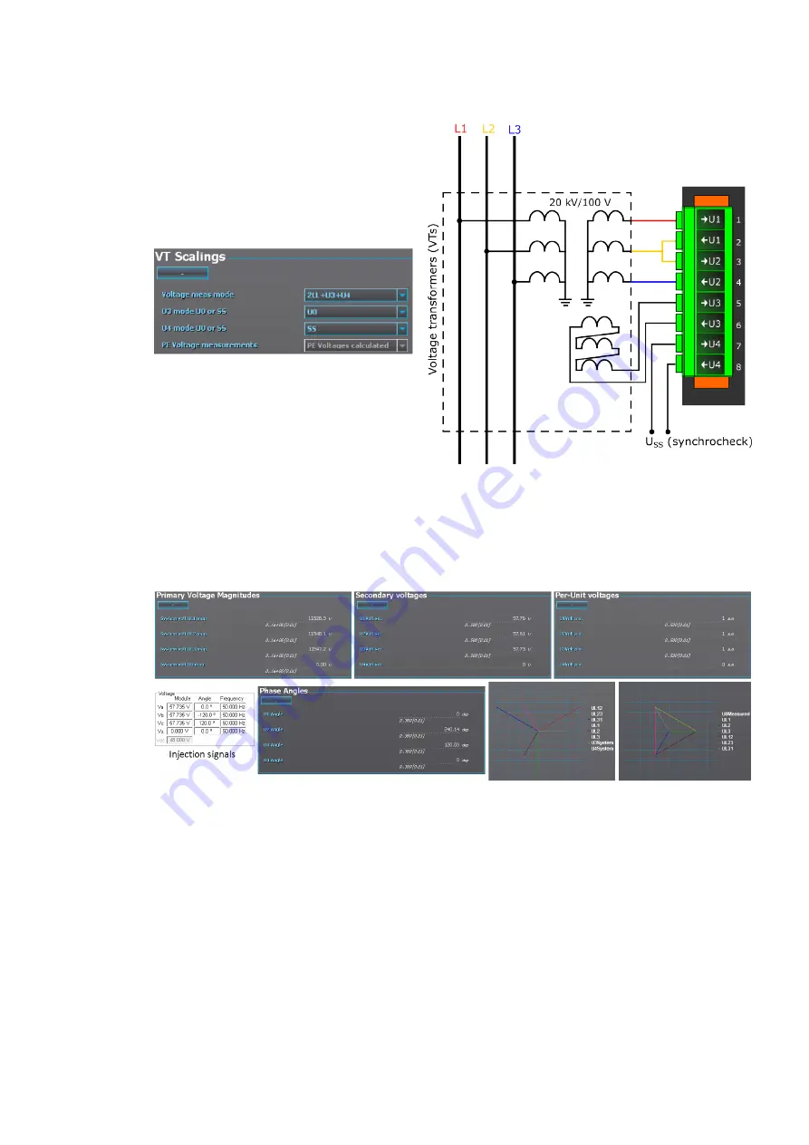
Figure. 5.2.2 - 71. 2LL+U0+SS settings and connections.
The image collection below presents the relay's behavior when nominal voltage is injected into the relay
via secondary test equipment. The measurement mode is 3LN+U4 which means that the relay is
measuring line-to-neutral voltages. The VT scaling has been set to 20 000 : 100 V. The U4 channel
measures the zero sequence voltage which has the same ratio (20 000 : 100 V).
Figure. 5.2.2 - 72. Relay behavior when nominal voltage injected.
The image collection below presents the relay's behavior when voltage is injected into the relay via
secondary test equipment during an earth fault. The measurement mode is 3LN+U4 which means that
the relay is measuring line-to-neutral voltages. The VT scaling has been set to 20 000 : 100 V. The U4
channel measures the zero sequence voltage which has the same ratio (20 000 : 100 V).
A
AQ
Q-F215
-F215
Instruction manual
Version: 2.04
75
Содержание AQ-F215
Страница 1: ...AQ F215 Feeder protection IED Instruction manual ...
Страница 430: ...Figure 7 4 261 Example block scheme A AQ Q F215 F215 Instruction manual Version 2 04 429 ...
Страница 452: ...Figure 8 14 284 Panel cutout dimensions and device spacing A AQ Q F215 F215 Instruction manual Version 2 04 451 ...
Страница 487: ...10 Ordering information A AQ Q F215 F215 Instruction manual Version 2 04 486 ...