


Table. 5.3.12 - 119. Measured magnitude selection settings.
Name
Description
Range
Step Default
Measured
magnitude
Selection of P-P or P-E voltages. Additionally, the U3 or U4 input can be
assigned as the voltage channel to be supervised.
0: P-P
voltages
1: P-E
voltages
2: U3 input
(2LL-U3SS)
3: U4 input
(SS)
-
0: P-P
voltages
The selection of the AI channel in use is made with a setting parameter. In all possible input channel
variations the pre-fault condition is presented with a 20 ms averaged history value from -20 ms from
START or TRIP event.
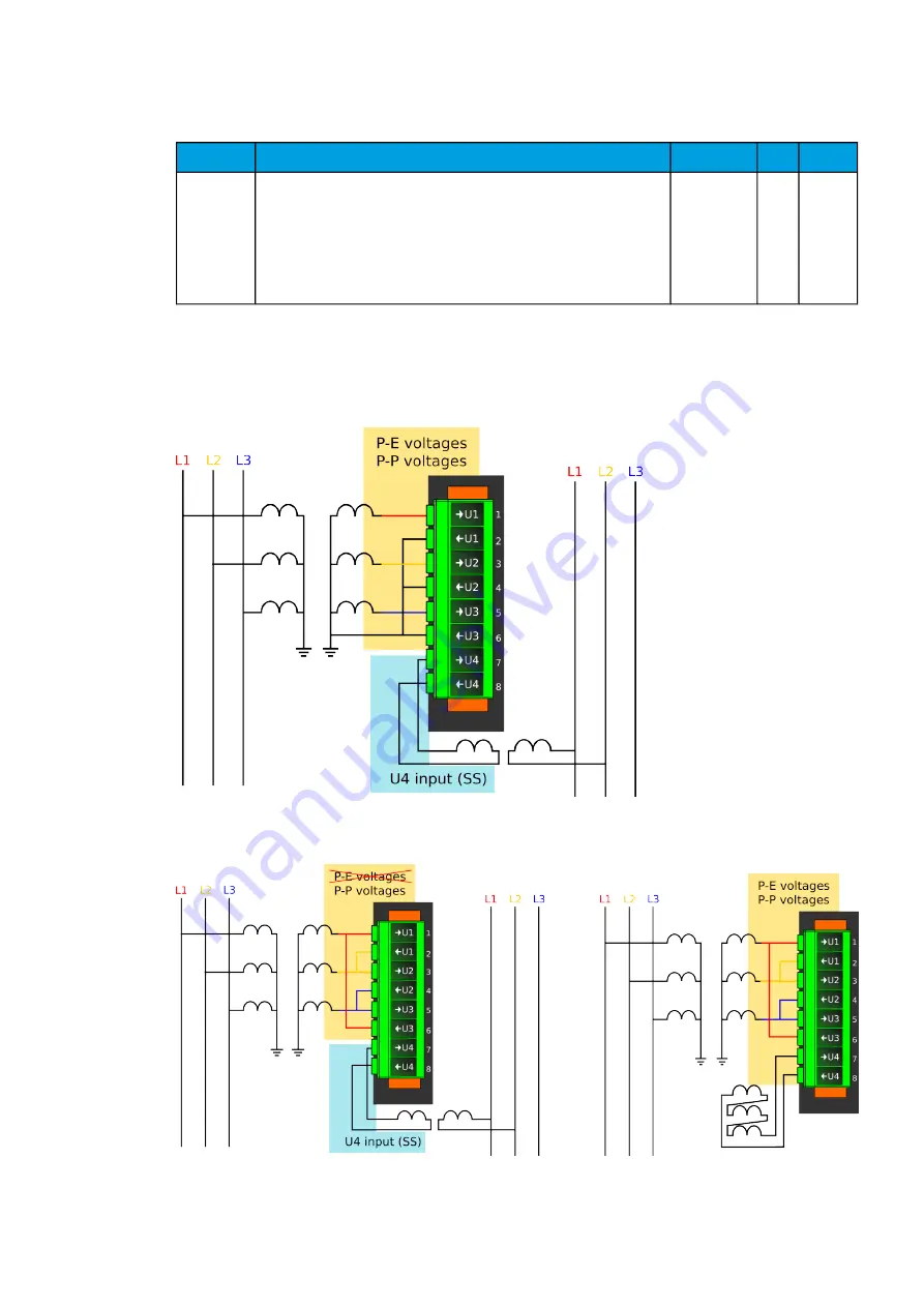
Figure. 5.3.12 - 130. Selectable measurement magnitudes with 3LN+U4 VT connection.
Figure. 5.3.12 - 131. Selectable measurement magnitudes with 3LL+U4 VT connection (P-E voltages not available without
residual voltage).
A
AQ
Q-F215
-F215
Instruction manual
Version: 2.04
187
Содержание AQ-F215
Страница 1: ...AQ F215 Feeder protection IED Instruction manual ...
Страница 430: ...Figure 7 4 261 Example block scheme A AQ Q F215 F215 Instruction manual Version 2 04 429 ...
Страница 452: ...Figure 8 14 284 Panel cutout dimensions and device spacing A AQ Q F215 F215 Instruction manual Version 2 04 451 ...
Страница 487: ...10 Ordering information A AQ Q F215 F215 Instruction manual Version 2 04 486 ...