


25
10. BOILER
OPERATION
WITH
"PUFFER" OR COMBO PUFFER
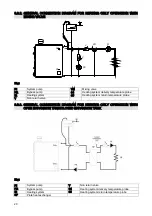
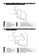
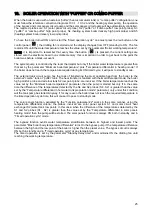
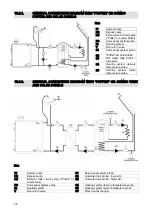
When the boiler is used with an external “puffer” (heat accumulator tank) or “combo puffer” configuration, one
must follow the reference connection diagrams 10.3.1 – 10.3.2 and the heating system pump;, the operation
of the bypass and solar panels circuit pump and the solar panels circuit pump will be automatically controlled.
The required probes are: S1 (solar panel circuit probe), S2 (“puffer” or “combo puffer” low point probe), S3
(“puffer” or “combo puffer” high point probe), S4 (heating system boiler delivery high point probe) and S5
(heating system boiler delivery low point probe).
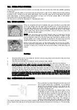
To have the boiler turned ON and to start the "timed operation cycle" one must press the red button on the
control panel (
); the drafting fan is started and the display changes from OFF (standby) to ON. The fan
remains ON until the water temperature reaches the value set by the parameter “Boiler working temperature”.
NOTE: it is important to remember that every time the button (
) is pressed, the current settings are
stored onto the electronic board non volatile memory; this is important in order to get back to the point the
boiler was before a black-out event.
The system pump is controlled by the room thermostat but only if the boiler water temperature is greater than
that set by the parameter “Minimum boiler temperature” plus “Temperature differential in heating mode”. If
the boiler does not reach the temperature required during its ON timed cycle, it will pass to standby mode.
The external tank circuit pump has the task of transferring the most possible heat from the boiler to the
external “combo” tank or “puffer” tank. The heat transfer is realized with thermal differential mode; the boiler
high point S4 probe and external tank S2 low point probe are involved. If the boiler temperature reaches the
value set by the “Minimum boiler temperature” parameter, then the pump is started but only if in the same
time the difference of the temperatures detected by the S4 and S2 probes (S4 – S2) is greater than the value
set by the “Temperature differential in hot water tank preparation mode” parameter; only under this condition
will the tank pump be started. Anyway, if for any reason the boiler does not reach the required temperature in
the timed operation cycle time, this will cause it to pass to standby mode.
The solar panels function, activated by the “Function parameter #2” works in the same manner, using the
temperature differential criteria; the probes involved are solar panel system S1 and solar circuit heat
exchanger S2 (water tank low point). In this case, when the difference of the temperatures detected by the
S1 and S2 probes (S1 – S2) is greater than the value set by the “Temperature differential in solar panels
heating mode” then the pump will be started. The solar panels function is always ON both in standby and in
“Timed operation cycle” mode.
The bypass function avoids water temperature stratification between its highest and lowest points. The
parameter “Max boiler body temperature differential” turns On the bypass pump if the temperature difference
between the high and the low point of the boiler is higher than the preset value. The bypass circuit is always
ON both in standby and in “Timed operation cycle” at any temperature.
The timed operation is set by the parameter "Standby delay time" and maintains ON the drafting fan until
reaching the working temperature.
Содержание ASPIRO A 29 R/SA
Страница 1: ...ASPIRO Installation Operation Maintenance www arcacaldaie com ...
Страница 2: ...2 ...


