Section 3 - Electrical Connections and Setup
Page 11
MULTI-PARAMETER TRANSMITTER USER’S MANUAL
Section 3 - Electrical Connections and Setup
3.10 MANUAL TEST MODE
(LCD MENU SECTIONS - pH: 4.4, ORP: 5.3, Conductivity: 6.4, Flow: 7.2)
The setup can be tested using Manual Test Mode to simulate process changes.
MANUAL TEST MODE is used to simulate a process reading in order to verify the correct
response of the output.
3.11 4-20 mA Isolated Output
(LCD MENU SECTIONS - pH: 4.15, ORP: 5.14, Conductivity: 6.16, Flow: 7.14)
The Transmitter has a single 4 to 20mA output, electrically isolated from the ground. The output
can source current into a resistive load. Maximum resistance depends on supply voltage.
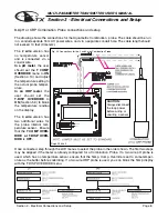
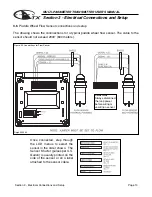
Drawing on page 6 (Fig. 3.1)
The output is dedicated to track the process and has fully independent and fully adjustable 4 &
20 mA output setpoints. This will enable the operator to span the output over the desired range.
The output can be precisely trimmed through the LCD menu for precision applications.
The drawing on page 6 (Fig. 3.1) shows the connections for the output.
Wire Specification: 22 AWG 7/30, insulation 0.010”


