VIPAC-8XX Series User Manual
21
4. BT1:
Power on/off button
, They are used to connect power switch button. The two pins are
disconnected under normal condition. You may short them temporarily to realize
system startup & shutdown or awaken the system from sleep state.
5. DC_OUT:
(1x4 Pin Connector),DC+12V and DC+5V System power
output
connector.
Pin#
Power output
Pin1
DC+12V
(
DC12V_S0
)
Pin2
Ground
Pin3
Ground
Pin4
DC+5V(DC5V_S0)
Note:
DC+5V Output current of the connector must not be above 0.5A.
DC+12V Output current of the connector must not be above 1A.
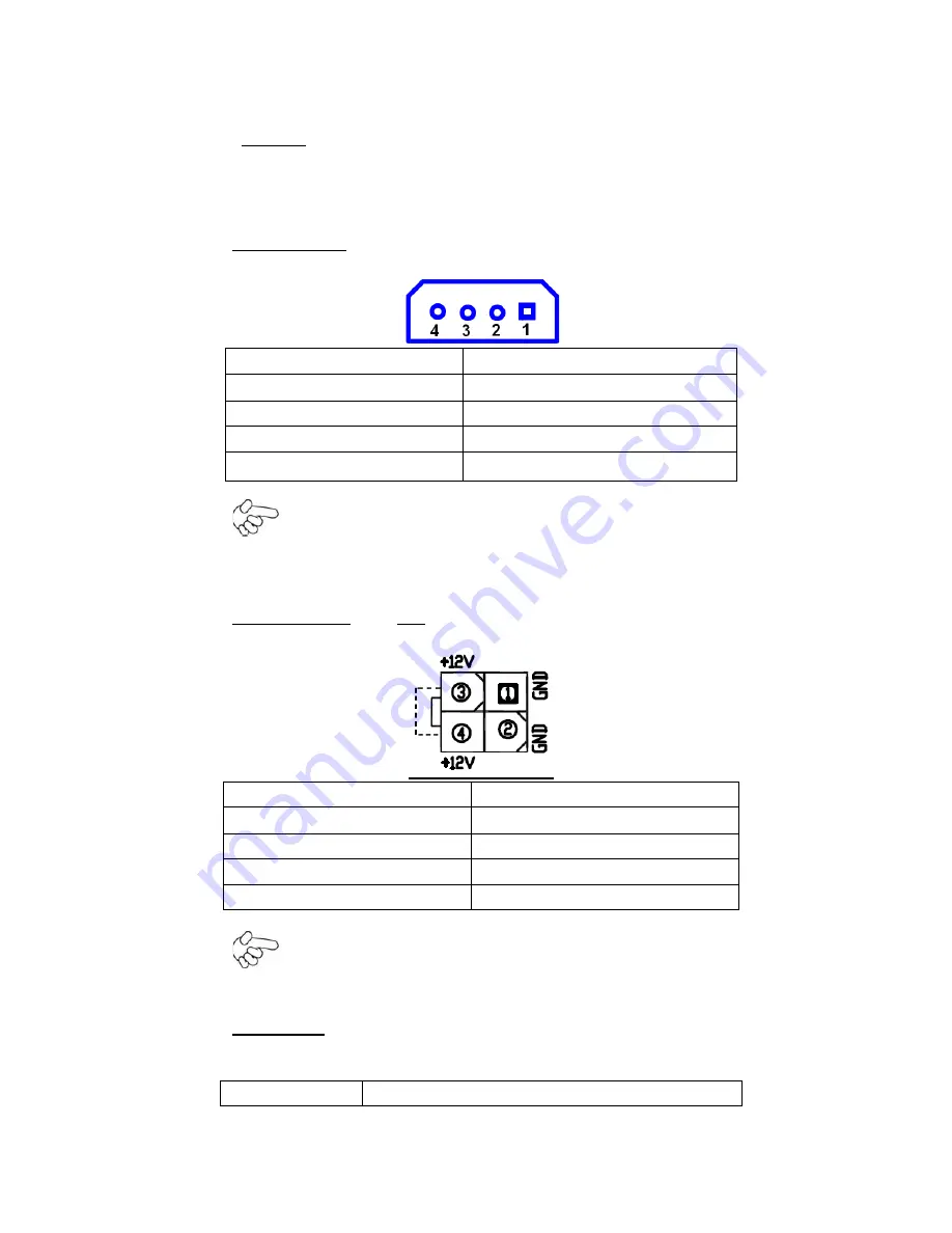
6. ATX12V_IN(
option
):
(5.50mm Pitch 2x2 Pin Connector),DC12V System power output connector
。
Pin#
Power output
Pin1
Ground
Pin2
Ground
Pin3
DC12V_S5
Pin4
DC12V_S5
Note:
DC+12V Output current of the connector must not be above 1A.
7. CPU1:
(FCBGA1170), onboard Intel Bay trail-I/M Processors.
Processor
Содержание VIPAC-8 Series
Страница 11: ...VIPAC 8XX Series User Manual 10 Figure 1 3 Dimensions of VIPAC 817 Figure 1 4 Dimensions of VIPAC 821 ...
Страница 18: ...VIPAC 8XX Series User Manual 17 2 2 Motherboard Layout Figure 2 1 Motherboard ASB M7102 Layout ...
Страница 20: ...VIPAC 8XX Series User Manual 19 Board Bottom Figure 2 3 Motherboard bottom draw of ASB M7102 ...
Страница 61: ...VIPAC 8XX Series User Manual 60 Step 5 Click Finish to exit the wizard ...
Страница 64: ...VIPAC 8XX Series User Manual 63 Step 5 Click Next to continue Step 6 Click Next to continue ...
Страница 70: ...VIPAC 8XX Series User Manual 69 Step 5 Click Finish to complete the installation ...
Страница 74: ...VIPAC 8XX Series User Manual 73 Step 7 Click Finish to complete installation ...


