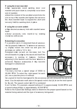
background image

d)

e)

f)

g)

5)

Safety instructions for all operations
Safety warnings common for grinding, sanding, wire brushing, polishing, carving or 
abrasive cutting-off operations:
a)

NOTE List only those operations that are applicable.
NOTE List only those operations that were not included in the first warning. If all 
listed operations are applicable, then this warning is omitted, but all subsequent 
warnings are given without exclusion.
b)

c)

d)

e)

c)

d)

e)

3)
a)

b)

c)

d)

e)

f)

g)

4)
a)

b)

c)

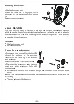
Removing Accessories

Using  Mandrels

The most common types of mandrel to use with this tool are the standard mandrel 
which is used with cutoff discs, grinding wheels, emery wheels, and cut-off wheels. 
Screw mandrels are used with polishing wheels and polishing drums. Drum mandrel 
are used with sanding drums.

To install:

If using the standard mandrel:

NOTE: The mandrel washer should be placed between the mandrel screw and the 
accessory.

f)

g)

                                                                                           
h)

i)

j)

k)

l)

m)

n)

o)

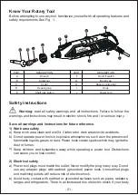
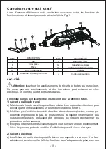
Know Your Rotary Tool

Before attempting to use any tool, familiarize yourself with all operating features and 
safety requirements.See Fig.  1.

Safety instructions

        Warning: read all safety warnings and all instructions. Failure to follow the 
warnings and instructions may result in electric shock, fire and / or serious injury.                                                    

Save all warnings and instructions for future reference.
1)
a)
b)

c)

2)
a)

b)

p)

q)

r)

s)

Further safety instructions for all operations 
Kickback and related warnings

Kickback is a sudden reaction to a pinched or snagged rotating wheel, sanding 
band, brush or any other accessory. Pinching or snagging causes rapid stalling of 
the rotating accessory which in turn causes the uncontrolled power tool to be forced 
in the direction opposite of the accessory’s rotation.
For example, if an abrasive wheel is snagged or pinched by the workpiece, the edge 
of the wheel that is entering into the pinch point can dig into the surface of the 
material causing the wheel to climb out or kick out. The wheel may either jump 
toward or away from the operator, depending on direction of the wheel’s move- ment 
at the point of pinching. Abrasive wheels may also break under these conditions.
Kickback is the result of power tool misuse and/or incorrect operating procedures or 
conditions and can be avoided by taking proper precautions as given below.
a)

b)

c)

d)

e)

Additional safety instructions for grinding and cutting-off 
operations 
Safety warnings specific for grinding and abrasive 
cutting-off operations:

a)

b)

c)

d) 

e)

f)

g)

h)

Additional safety instructions for wire brushing operations 
Safety warnings specific for wire brushing operations:

a)

b)

c)

TECHNICAL   SPECIFICATIONS

        WARNING
Always wear eye protection when using this tool. Failure to do that could result in 
objects being thrown into your eyes and cause possible serious injury.

        WARNING
Do not use any attachments or accessories not recommended by the manufacturer 
of this product. The use of attachments or accessories not recommended can result 
in serious personal injury.

Applications

You may use this product for the purposes listed below:

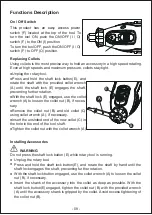
Functions Description

On / Off Switch

Replacing Collets
Using collets is the most precise way to hold an accessory in a high speed rotating. 
Even at high speeds and maximum pressure, collets stay tight.

Installing Accessories

          WARNING
Do not press the shaft lock button (E) while rotary tool is running.

Rules of Operating Speeds

The best way to determine the correct speed for work on any material is to practice 
for a few minutes on a piece of scrap, even after referring to the Speed Dial Settings 
tables. You can quickly learn that a slower or faster speed is more effective just by 
observing what happens when you make a pass or two at different speeds.
When working with a scrap piece of plastic, start at a slow rate of speed and increase 
the speed until you observe whether the plastic is melting at the point of contact; 
reduce the speed slightly to get optimum working speed without melting the 
workpiece.

Certain materials, some plastics for example, require a relatively slow speed 
because at high speed the friction of the tool generates heat and causes the plastic 
to melt.

Slow speed operation (15,000 RPM or less) is usually best for polishing operations 
using the felt polishing accessories, delicate wood carving and fragile model parts. 
All brush applications require lower speeds to avoid wire discharge from the holder. 
Allow the tool to do the work for you when using lower speed settings.

Higher speeds are better for drilling, carving, cutting, routing, shaping, and cutting 
dadoes or rabbets in wood. Hardwoods, metals and glass also require high speed 
operation.

NOTE:

Detailer’s Grip Attachment 

Installation Instructions
1.

2.

Plastic and materials that could melt at low temperatures should be cut at low 
speeds.
Soft wood should be cut at high speed.
Aluminum, tin, copper, lead, and zinc alloys may be cut at any speed, depending 
on the type of cutting being done. Use paraffin or other suitable lubricant on the 
cutter to prevent the cut material from adhering to the cutter teeth.

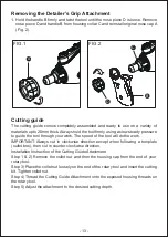
Remove the nose cap A from the end of the tool and set nose cap aside. The 
original nose cap must be reinstalled when this attachment is not used (Fig. 1).
Place handle B over housing collar C with the handle in the desired position and 
securely tighten the handle B with the nose piece D that’s provided with handle 
(Fig. 2).
Make sure detailer’s grip is fully secured before using tool.


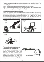
Step 2. 
Step 3. 

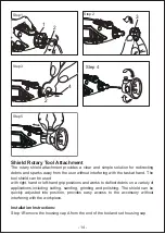
Using the Shield Rotary Tool Attachment:
Always turn the tool off before adjusting position, changing accessory and removing 
attachment. Rotary Tools cut, sand, grind, and polish in many directions. To 
accommodate the Rotary Tool’s Maneuverability, the Shield can be quickly 
positioned and repositioned with a turn to the right or left .To extend the life of the 
Shield periodically clean with a soft bristle brush or compressed air.

Flexible Driver Attachment

Safety Rules for Flexible Driver                  

aside. The original housing cap must be reinstalled when this attach- ment is not 
used (Fig.1).
          Screw the Shield onto the tool using the lock nut B (Fig.2).
         Position the Shield such that it will redirect debris, sparks, and dust away 
from the user using the positioning tabs C (Fig.3).

Driver to disengage from the tool. The minimum recommended bend radius is 6”

15CM

.

Always hold the hand piece firmly in your hands during the start-up. The reaction 
torque of the motor, as it accelerates to full speed, can cause the shaft to twist. 
Not for use with router bits or other large diameters (1” or larger) bits. Large diame- 
ter bits can cause kickback and loss of control when used with the Flexible Driver. 
Do not remove end ferrule while tool is running. The cable will become loose from 
the jacket and will uncontrollably whip or lash around.

Installation Instructions

It is extremely important to carefully read and follow the directions below to 
assemble the Flexible Driver to your rotary to ensure the tool will function properly.
                                                                                                                                      

Operating Instructions

 it back into the shaft. To prevent damage to tool do not over grease shaft.
Too much grease will cause the unit to overheat. Reattach the Flexible Driver to the 
rotary tool.

Cleaning, maintenance

Always pull out the mains power plug before starting any cleaning work.

Cleaning

●Keep all safety devices, air vents and the motor housing free of dirt and dust as far 

as possible.
Wipe the equipment with a clean cloth or blow                   

●it with compressed air at low pressure.

We recommend that you clean the device immediately each time you                                              

●have finished using it.

Clean the equipment regularly with a moist cloth and some soft soap. Do not use 
cleaning agents or solvents; these could attack the plastic parts of the equipment. 
Ensure that no water can seep into the device.

Maintenance
There are no parts inside the equipment which require additional maintenance.

Environmental Protection

- 12 -

Содержание M6

Страница 1: ...User Manual Corded Rotary Tool Model M6 ...

Страница 2: ...English Français Español 01 18 19 37 38 56 Contents ...

Страница 3: ... liquids gases or dust Power tools create sparks which may ignite the dust or fumes Keep children and bystanders away while operating a power tool Distractions can cause you to lose control Electrical safety Power tool plugs must match the outlet Never modify the plug in any way Do not use any adapter plugs with earthed grounded power tools Unmodified plugs and matching outlets will reduce risk of...

Страница 4: ... the tool Carrying power tools with your finger on the switch or energizing power tools that have the switch on invites accidents Remove any adjusting key or wrench before turning the power tool on A wrench or a key left attached to a rotating part of the power tool may result in personal injury Do not overreach Keep proper footing and balance at all times This enables better control of the power ...

Страница 5: ...ar type of power tool taking into account the working conditions and the work to be performed Use of the power tool for operations different from those intended could result in a hazardous situation Service Have your power tool serviced by a qualified repair person using only identical replacement parts This will ensure that the safety of the power tool is maintained This power tool is intended to...

Страница 6: ...les generated by your operation Prolonged exposure to high intensity noise may cause hearing loss Keep bystanders a safe distance away from work area Anyone entering the work area must wear personal protective equipment Fragments of workpiece or of a broken accessory may fly away and cause injury beyond immediate area of operation Hold power tool by insulated gripping surfaces only when performing...

Страница 7: ...lothing pulling the accessory into your body Regularly clean the power tool s air vents The motor s fan will draw the dust inside the housing and excessive accumulation of powdered metal may cause electrical hazards Do not operate the power tool near flammable materials Sparks could ignite these materials Do not use accessories that require liquid coolants Using water or other liquid coolants may ...

Страница 8: ...ition your hand in line with and behind the rotating wheel When the wheel at the point of operation is moving away from your hand the possible kickback may propel the spinning wheel and the power tool directly at you When wheel is pinched snagged or when interrupting a cut for any reason switch off the power tool and hold the power tool motionless until the wheel comes to a complete stop Never att...

Страница 9: ... easily penetrate light clothing and or skin Allow brushes to run at operating speed for at least one minute before using them During this time no one is to stand in front or in line with the brush Loose bristles or wires will be discharged during the run in time Direct the discharge of the spinning wire brush away from you Small particles and tiny wire fragments may be discharged at high velocity...

Страница 10: ...e shaft preventing further rotation With the shaft lock E engaged use the collet wrench A to loosen the collet nut B if neces sary Remove the collet nut B and old collet C using collet wrench A if necessary Insert the unslotted end of the new collet C in the hole in the end of the tool shaft Tighten the collet nut with the collet wrench A Unplug the rotary tool Press and hold the shaft lock button...

Страница 11: ...aced between the mandrel screw and the accessory Unplug the rotary tool With the shaft lock E engaged loosen the collet nut B with the provided wrench A Remove the accessory Press and hold the shaft lock button E Insert the slot end of the provided wrench into the slot on top of the mandrel and unscrew Remove mandrel screw and washer Place desired accessory over mandrel shaft and align accessory h...

Страница 12: ...et nut and run the rotary tool You should be able to judge by the sound and feel if the accessory is running in balance Continue adjusting in this fashion until the best balance is achieved Replace accessories if they become damaged or unbalanced Speed Control The rotary tool has a speed range of 10000 to 35 000 RPM To select the right speed for each job use a practice piece of material Vary speed...

Страница 13: ...wheel Diamond Grinding Needle Sanding band 10 20 Spiral Cutting Bit 12 25 15 32 25 30 15 32 10 25 10 20 12 25 15 32 25 30 15 32 10 25 10 20 25 35 25 35 12 25 15 32 15 30 25 32 15 32 10 25 10 20 25 35 25 35 12 25 25 32 15 32 10 25 10 20 25 35 25 35 12 25 25 32 15 32 10 25 Aluminum brass etc 10 20 25 35 25 35 25 35 12 25 25 32 15 32 10 25 10 20 25 35 12 25 25 32 15 32 10 25 10 20 1 2 3 4 5 MAX 10 12...

Страница 14: ...model parts All brush applications require lower speeds to avoid wire discharge from the holder Allow the tool to do the work for you when using lower speed settings Higher speeds are better for drilling carving cutting routing shaping and cutting dadoes or rabbets in wood Hardwoods metals and glass also require high speed operation NOTE Detailer s Grip Attachment Installation Instructions 1 2 Pla...

Страница 15: ...se direction Installation Instruction of the Cutting Guide Attachment Step 1 2 Remove the collet nut and then the housing cap from the end of your rotary tool Step 3 Place the collet nut loosely on the end of the rotary tool and insert the cutting bit Tighten collet nut Step 4 Thread the Cutting Guide Attachment onto the exposed housing threads on the rotary tool Step 5 Adjust the attachment to th...

Страница 16: ... right hand or left hand grip positions and works to deflect debris on a variety of applications including cutting sanding grinding and polishing The shield can be quickly adjusted into position provides easy access to the accessory without interfering with the workpiece Installation Instructions Step 1 Remove the housing cap A from the end of the tool and set housing cap Step 3 Step 2 3 Step 1 1 ...

Страница 17: ...lexible Driver Attachment Safety Rules for Flexible Driver aside The original housing cap must be reinstalled when this attach ment is not used Fig 1 Screw the Shield onto the tool using the lock nut B Fig 2 Position the Shield such that it will redirect debris sparks and dust away from the user using the positioning tabs C Fig 3 Fig 3 C C B Fig 2 Do not operate the flexible shaft with a sharp or ...

Страница 18: ...move end ferrule while tool is running The cable will become loose from the jacket and will uncontrollably whip or lash around Installation Instructions It is extremely important to carefully read and follow the directions below to assemble the Flexible Driver to your rotary to ensure the tool will function properly 1 Remove the shaft collar 2 Loosen the collet nut 3 Raise the handle end of gently...

Страница 19: ...her than the working end of the Flexible Driver Flexible Shaft Lubrication The flexible driver should be lubricated after every 25 30 hours of use To lubricate Unscrew the flexible driver assembly from the motor housing Pull the center core out of the flexible driver assembly Wipe a very thin film automotive wheel bearing grease on to the center core and reinsert 8 fastened 6 Insert the hex key in...

Страница 20: ...th compressed air at low pressure We recommend that you clean the device immediately each time you have finished using it Clean the equipment regularly with a moist cloth and some soft soap Do not use cleaning agents or solvents these could attack the plastic parts of the equipment Ensure that no water can seep into the device Maintenance There are no parts inside the equipment which require addit...

Страница 21: ...ôle de vitesse Crochet Cordon d alimentation sécurite du lieu de travail Maintenez le lieu de travail propre et bien eclaire Les risques d accident sont plus eleves quand on travaille dans un endroit encombre ou sombre N utilisez pas d outil électroportatif dans des atmospheres explosives comme par exemple en presence de gaz de poussières ou de liquides inflammables Les outils électroportatifs pro...

Страница 22: ... causer des blessures corporelles graves Utilisez des équipements de sécurite personnelle Portez toujours une protection oculaire Le port d équipements de sécurite tels que des masques antipous sières des chaussures de sécurite antiderapantes des casques de chantier et des protecteurs d oreilles dans des conditions appropriees reduira le risque de blessure corporelle Evitez les demarrages intempes...

Страница 23: ...z les outils électroportatifs dont vous ne vous servez pas hors de portee des enfants et ne permettez pas a des personnes qui ne connaissent pas l outil électroportatif ou qui ignorent ces consignes de s en servir Les outils électropor tatifs sont dangereux dans les mains d utilisateurs inexperimentes Entretenez les outils électroportatifs Verifiez que les pièces mobiles sont alignees correctement...

Страница 24: ...s de pongage ou de tous autres accessoires doit cor respondre exactement à celle de I axe de rotation ou a la douille de l outil électroportatif Les accessoires qui ne correspondent pas a la taille du materiel de montage de l outil électroportatif fonctionneront de maniere désé qui est librée avec des vibrations excessives et ils risqueraient de causer une perte de contrôle Les MEULES MONTEES a ma...

Страница 25: ...urs l outil fermement à la main ou avec les deux mains lors de la mise en marche Le couple de reaction du moteur lorsqull passe à la vitesse maximale risque de causer une rotation accidentelle de l outil Utilisez des brides de fixation pour soutenir l ouvrage chaque fois que cela est possible Ne tenez jamais un ouvrage de petites dimensions d une main et l outil de l autre main lorsque ce dernier ...

Страница 26: ...on de l outil électroportatif Le ventilateur du moteur attirera de la poussière à intérieur du carter et une accumu lation excessive de métal en poudre pourrait causer des dangersélectriques N utilisez pas l outil électroportatif à proximité de materiaux inflammables Des étincelles risqueraient de mettre le feu à ces materiaux N utilisez pas d accessoires qui necessitent des liquides de refroidiss...

Страница 27: ...e meule Ne tentez pas de realiser une coupe de profond eur excessive Ceci causerait une augmentation de la charge et le risque de voir la meule se tordre ou s accrocher dans la rainure avec comme consequence possible un choc en retour ou la cassure de la meule Ne positionnez pas votre main dans la trajectoire de la meule en rotation ou derriere celle ci Lorsque la meule au point de fonctionnement ...

Страница 28: ...es murs existants ou dans d autres endroits sans visibilité La meule saillante risque de couper une canalisation d eau ou de gaz des fils électriques ou des objets pouvant causer un choc en retour Tenez toujours compte du fait que des poils des brosses se detachent et sont projetes par les brosses meme dans des conditions de fonctionnement normales N aggravez pas ce problème en faisant pression ex...

Страница 29: ...teur ON OFF I O F sur ON I position Pour éteindre I outil poussez I interrupteur marche arret I O F sur OFF Position O Débrancher I outil rotatif Appuyez sur le bouton de vérrouillage de I arbre E et maintenez le enfoncé puis faites tourner I arbre avec la cle de serrage fournie A jusqu a ce que le verrou de I arbre E s enclenche I arbre empechant la poursuite de la rotation Le verrouillage de l a...

Страница 30: ...s la pince aussi profondément que possible Le bouton de verrouillage de l arbre E étant engagé serrez l écrou de la bague B à l aide de la clé fournie A jusqu à ce que la tige de l accessoire soit saisie par la bague Évitez de trop serrer l écrou de la douille B Debrancher I outil rotatif Installez le mandrin Appuyez sur le bouton de verrouillage de I arbre E et maintenez le enfonce Inserer I extr...

Страница 31: ... 4 po Resserrer I ecrou de serrage et fa ire tourner I outil rotatif Vous devriez être capable de juger par le son et sentir si I accessoire est en equilibre Continuez à ajuster de cette façon jusqu a ce que le meilleur équilibre soit atteint Remplacez les accessoires s ils sont endommages ou desequilibres contrôle de vitesse L outil rotatif a une plage de vitesse de 10000 à 35 000 tr min Pour sél...

Страница 32: ...de meulage Bande de ponçage 10 20 Spiral schneider 12 25 15 32 25 30 15 32 10 25 10 20 12 25 15 32 25 30 15 32 10 25 10 20 25 35 25 35 12 25 15 32 15 30 25 32 15 32 10 25 10 20 25 35 25 35 12 25 25 32 15 32 10 25 10 20 25 35 25 35 12 25 25 32 15 32 10 25 Aluminium laiton etc 10 20 25 35 25 35 25 35 12 25 25 32 15 32 10 25 10 20 25 35 12 25 25 32 15 32 10 25 10 20 1 2 3 4 5 MAX 10 12RPM 12 25 15 32...

Страница 33: ... les applications de brosse necessitent des vitesses inférieures pour eviter la decharge du fil du support Laissez I outil effectuer le travail pour vous lorsque vous utilisez des paramêtres de vitesse inferieure Des vitesses plus elevees sont meilleures pour percer decouper couper achemin er façonner et couper des dadoes ou des feuillures dans le bois Les bois durs les metaux et le verre nécessit...

Страница 34: ...iguilles d une montre Instruction d installation pour l accessoire de guide de coupe Étape 1 et 2 Retirez l écrou de la pince et ensuite le capuchon du boîtier à l extrémité de l outil rotatif Étape 3 Placer l écrou de serrage sur l extrémité de l outil rotatif et insérer le foret Serrer l écrou de la pince Étape 4 Enfilez l accessoire du guide de coupe sur les filets exposés du carter de l outil ...

Страница 35: ... 33 Step 3 Step 2 3 Step 1 1 2 2 4 Step 4 Step 5 20 15 10 ...

Страница 36: ...e Le couvercle du boitier d origine doit être reinstalle lorsque cette piece n est pas utilisée Fig 1 Etape 2 Vissez le blindage sur I outil a I aide du contre écrou B Fig 2 Etape 3 Positionnez le bouclier de sorte qu il redirige les debris les étincelles et la poussières de I utilisateur en utilisant les languettes de positionnement C Fig 3 Utilisation de accessoire de bouclier rotatif Toujours é...

Страница 37: ...diamêtre peuvent provoquer un rebond et une perte de contrôle lorsqu ils sont utilisés avec I arbre flexible Ne pas retirer la bague d extremite lorsque I outil est en marche Le cable va se détacher de la veste et va fouetter ou fouetter de maniere incontrolable instructions d installation Pour fixer correctement I arbre flexible a I outil rotatif N utilisez pas I arbre flexible avec des coudes po...

Страница 38: ...taire du noyau interne génère des frottements excessives et la surchauffe 5 Visser le collier de montage de l arbre flexible sur l outil rotatif 6 Insérez la clé hexagonale dans le trou de la poignée 7 a b Desserrez l écrou de la douille puis insérez la tige de l accessoire dans la douille 8 Serrer l écrou du collier et vérifier tous les raccords pour s assurer qu ils sont solidement fixés 36 ...

Страница 39: ...ible fonctionner à grande vitesse votre outil rotatif en position verticale pendant 2 minutes avant utilisation Fig Desengagement de I arbre flexible L arbre flexible peut se desengager si le moteur de votre outil rotatif n est pas sureleve Plus haut que I extremite de travail de I arbre flexible Lubrification d arbre flexible L arbre flexible doit être lubrifie après 25 30 heures d utilisation Po...

Страница 40: ...SCRIPCIÓN Interruptor encendido apagado Tapa de cepillo Dial de control de velocidad Gancho Cable de fuente de alimentación La area de trabajo seguro Mantenga la area de trabajo limpia y iluminada clara Las areas desordenadas u oscuras van a invitar a accidentes No utilice herramientas eléctricas en atmosferas explosivas como en presencia de liquidos gases o polvo inflamables Las herramientas eléc...

Страница 41: ... de drogas alcohol o medicamentos Un momen to de falta de atenclon mientras opera las herramientas elec tri cas puede ocaslonar leslones personales graves Use equipo de protección personal Use siempre protección de los ojos El equipo de protección por ejemplo una más cara antipolvo calzado de seguridad antideslizante casco o protección de oídos utilizado para las condiciónes apropia das reducira l...

Страница 42: ...a que las personas que no estén familiarizadas con la herramienta eléctrica o estas instrucclones operen la herramienta eléctrica Las herramientas eléctricas son peligrosas en manos de usuarlos no entrenados Mantenidos las herramientas eléctricas Compruebe si hay desalineaclon o atascamiento de piezas móviles roturas de piezas y cualquier otra condición que pueda afectar el funclonamiento de las h...

Страница 43: ...ominal pueden romperse y romperse El diametro exterlor y el grosor de su accesorio deben estar dentro del rango de capacidad de su herramienta eléctrica Los accesorios de tamaño incorrecto no se pueden controlar adecuadamente El tamaño del eje de las ruedas tambores de lijado o cualqui er otro accesorio debe encajar correctamente en el husillo o collar de la herramienta eléctrica Los accesorios qu...

Страница 44: ...eléctrica al operador Siempre sostenga firmemente la herramienta en su s mano s durante el arranque El par de reacclon del motor a medida que acelera a la velocidad máxima puede causar que la herramienta se tuerza Use abrazaderas para apoyar la pieza de trabajo siempre que sea practico Nunca sostenga una pieza de trabajo pequena en una mano y la herramienta en la otra mientras este en uso Sujetar ...

Страница 45: ...sgos eléctricos No opere la herramienta eléctrica cerca de materiales inflamables Las chispas podrían encender estos materiales No use accesorios que requieran liquidos refrigerantes El uso de agua u otros liquidos refrigerantes puede provocar electrocución o golpes Mantenga un agarre firme de la herramienta eléctrica y posiclone el cuerpo y el brazo de manera que le permitan resistir las fuerzas ...

Страница 46: ...eso o rotura de la rueda No posicióne la mano en linea con la rueda que rota ni detras de ella Cuando la rueda en el punto de operación se este moviendo alejandose de la mano el posible retroceso podra impulsar la rueda que gira y la herra mienta eléctrica directa mente hacia usted Cuando la rueda se fue aprietada se engancha o cuando se interrumpe un corte por algun motivo apague la herramienta e...

Страница 47: ...ble aislamiento agua cables eléctricos u objetos que pueden causar retroceso Tenga presente que el cepillo lanza cerdas de alambre inclu so durante la operación ordinaria No someta los alambres a un esfuerzo excesivo aplicando una carga excesiva al cepillo Las cerdas de alambre pueden penetrar facilmente en la ropa ligera y o la piel Deje que los cepillos giren a la velocidad de Funciónamiento dur...

Страница 48: ...PAGAR O posición Desenchufe la herramienta rotativa Presionado el botón de bloqueo del eje E y gire el eje con la llave de collar suministrada A hasta que el bloqueo del eje E se enganche el eje impidiendo una mayor rotaclon Con el bloqueo del eje E enganchado use la llave de collar A para aflojar la tuerca del collar B si es necesarlo Perforación Retire la tuerca del collar B y el collarin viejo ...

Страница 49: ...el accesorio Evite el exceso de ajuste de la tuerca del collar B Desenchufe la herramienta rotativa Instalar el mandril Mantenga preslonado el botón de bloqueo del eje E Inserte el extreme de la ranura de la llave provista en la ranura en la parte superlor del mandril y desatornillar Desenchufe la herramienta rotativa Con el bloqueo del eje E enganchado afloje la tuerca del collar B con la llave p...

Страница 50: ... tuerca de la pinza y haga funclonar la herramienta rotativa Debena poder juzgar por el sonido y sentir si el accesorio esta Funciónando en equilibrlo Continue ajustando de esta manera hasta que se logre el mejor equilibrlo Reemplace los accesorios si se dahan o desequili bran Control de velocidad La herramienta rotativa tiene un rango de velocidad de 10000 a 35 000 RPM Para selecclonar la velocid...

Страница 51: ...ión Rueda de molienda Aguja de pulido de diamante Banda de lijado 10 20 12 25 15 32 25 30 15 32 10 25 10 20 12 25 15 32 25 30 15 32 10 25 10 20 25 35 25 35 12 25 15 32 25 30 25 32 15 32 10 25 10 20 25 35 25 35 12 25 25 32 15 32 10 25 10 20 25 35 25 35 12 25 25 32 15 32 10 25 Aluminlo latón etc 10 20 25 35 25 35 25 35 12 25 25 32 15 32 10 25 10 20 25 35 12 25 25 32 15 32 10 25 10 20 1 2 3 4 5 MAX 1...

Страница 52: ... el Plástico se derrita La operación a baja velocidad 15 000 RPM o me nos suele ser la mejor para las operaciones de pulido con los accesorios de pulido de fieltro la delicada talla de madera y las piezas fragiles del modelo Todas las aplicaciónes de cepillos requieren velocidades más bajas para evitar la descarga del cable del soporte Permita que la herramienta haga el trabajo por usted cuando us...

Страница 53: ... suelta en el extremo de la herramienta giratoria e inserte la broca de corte Apretar la tuerca del collar Paso 4 Enrosque el accesorio de la guía de corte en las roscas de la carcasa expuesta en la herramienta rotativa Paso 5 Ajuste el accesorio a la profundidad de corte deseada Retire la tapa de la punta del extremo de la herramienta y coloque la tapa de la nariz a un lado La tapa original de la...

Страница 54: ... 52 Step 3 Step 2 3 Step 1 1 2 2 4 Step 4 Step 5 20 15 10 ...

Страница 55: ...de la carcasa a un lado La tapa de la carcasa original debe reinstalarse cuando este accesorio no se utiliza Fig 1 Paso 2 Atornille el protector en la herramienta con la contratuerca B Fig 2 Paso 3 Coloque el protector de manera que redirija los desechos las chispas y el polvo del usuarlo utilizando las pestanas de posiciónamiento C Fig 3 Uso del accesorio de la herramienta Rotary Siempre apague l...

Страница 56: ...e se soltara de la chaqueta y se convertira en un latigazo o latigazo incontrolable Instrucciones de instalación Es extremadamente importante leer cuidadosamente y seguir las instrucciones a continuación para ensamblar el eje flexible en su rotativo para asegurar que la herramienta funcione correctamente Para acoplar correctamente el eje flexible a la herramienta rotativa TRES elementos deben extr...

Страница 57: ...onexiones estén aseguradas 4 a b Inserte el eje flexible interior al collar y luego apriete la tuerca del collar El anillo de metal en el núcleo interno debe estar al ras contra el mandril antes de apretarlo De lo contrario la longitud adicional del núcleo interno generará fricción y calor excesivos Anillo de metal Mandril 5 Atornille el collarín de montaje del eje flexible en la herramienta girat...

Страница 58: ...u nuevo accesorio de eje flexible funclone a alta velocidad en su herramienta giratoria en posiclon vertical durante 2 minutos antes de su uso Fig Desconexión del eje flexible El eje flexible puede soltarse si el motor de su herra mienta giratoria no esta elevado Más alto que el extremo de trabajo del eje flexible Lubricación flexible del eje El eje flexible debe lubricarse cada 25 30 horas de uso...

Страница 59: ...Sanding bands 12 7x12 7mm Sanding bands 6 3x12 7mm Sanding shanks 12 7mm ø3 2mm Sanding shanks 6 3mm ø3 2mm Drill ø1 6 2 3 3 2mm Diamond bit ø3 2mm Mandrel ø3 2mm Felt wheels 25 4x6 3mm Felt wheels 12 7x6 3mm Whet stone Carbon Brush Spanner L pin Brush ø3 2mm Hss cutter ø3 2mm Multipurpose cutting bit ø3 2mm Keyless Chuck 172 pcs Accessories with clear box ...

Отзывы: