8
6. Identify power supply connectors (680W version):
5.2 ATX 12V 4/8 Pin connector X 1
5.5 PCI-Express connector X 2
5.6 Floppy drive connector X 2
5.4 SATA drive connector X 4
5.3 PCI peripheral connector X 8
5.1 ATX 20/24 Pin connector X 1
500W version connectors: 1 x (20 + 4 pin) 1 x 12V (P4)
2 x SATA 8 x PCI 2 x Floppy
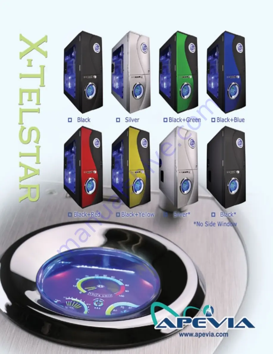
X-TELSTAR
Appearance after completing installation.
1
1. Motherboard installation:
1.1 Remove thumb screws from the
rear of the X-Telstar.
1.2
Push handle forward to release
latch, then open and remove the
left side panel.
NOTE: Processor, memory, and expansion card installation
is not covered in this manual. Please refer to each
components’ documentation for instructions.
3
4
5
2.1 To install a floppy drive, remove the
3 1/2" drive housing by placing an
index finger into each inlet. Push side
rails toward one another, then gently
lift and slide outward.
2.9 Align drive rails with inlets and slide
drive into place.
2.8 Locate 5 1/4" drive rails (inside
drive bay covers) and mount a
rail onto each side of the drive.
2.7 Remove 5 1/4" drive bay covers
by placing a finger into either
inlet, firmly pressing inward,
and opening.
2.6
Return cage to drive bay.
2.5 Align screw holes on the underside of the drive
cage with those on the hard drive, and fasten.
2.4 Slide hard drive into cage.
2.2 Remove (unscrew) slot cover from
the slot to be used. Replace with
floppy drive, secure screws on both
sides, and return to drive bay.
2.3 For hard drive installation, locate and
remove one of the drive cages from
the bay. Secure clasps between index
fingers and thumbs. Squeeze clasps
toward each other while pulling
outward to release.
3.1 Locate the fan flow connector coming
from the front panel(black/yellow).
Select fan(s) to be regulated. Connect
the 4-pin male fan connector to the fan
flow controller. Adjust knob on front
panel to control airflow. (Up to 5 fans
can be controlled via daisy chain.)
Note: You may also leave a sensor loose in the chassis in order to monitor
the ambient system temperature.
DO NOT
place the sensor directly on the
CPU as it may cause system damage.
2. Install 3½” and 5¼” drives:
3.2 Locate the two temperature probes
coming from the front panel. Determine
which wire is which is by holding one of
the sensors between index finger and
thumb for a few seconds. Look to the
front display and note whether the
TMPE1 or TMPE2 indicator is increasing.
Mark the wire for easy identification.
3.3 Place the TMPE1 probe on your CPUs heatsink.
Apply a small amount of tape to hold in place.
Use thermal tape for best results.
3. Connect fan flow controller and temperature probes:
4. LED display features:
4.1 The case fan monitor displays the current
fan use percentage.
(All screws and case keys are provided inside of the chassis.)
2
6
7
1.3 Remove the 2 thumb screws from the
motherboard tray area.
Release the
motherboard tray by sliding it in the
direction shown. Remove tray from
the chassis.
1.5
If your motherboard included an
IO shield, you must remove the
X-Telstar's IO shield. Use thumbs
or other object to push shield in-
ward (cover area with a cloth to
avoid injury from metal edges).
1.6
Remove a slot cover for each slot
that corresponds with your expansion
card setup. Return motherboard tray
to the chassis.
9
CONTENTS
1.
Motherboard installation..................................1
2.
Install 3½” and 5¼” drives
..............................3
3.
Connect fan flow controller and temperature probes....5
5.
Connect front panel leads to motherboard.....................7
6.
.....................8
Identify power supply connectors
1.4
Place motherboard on the tray. Make sure
there is a standoff screw in place for each
screw hole to be used on motherboard.
Align the motherboard with the standoff
screws and screw into place.
3.3 Place the TMPE2 probe on your hard disk drive.
Apply a small amount of tape to hold in place.
Use thermal tape for best results.
5. Connect front panel leads to motherboard:
3.1 Locate the USB/Audio/1394(Firewire)
front panel leads. Refer to your mother-
boards’ documentation for pin placement
instructions. Usually there is a triangular
marking on the lead to indicate the
positive wire.
6.1 Once all components have been installed properly, gently return
the side panels to their initial positions and replace the screws.
Congratulations! You have completed assembly of your X-Telstar.
7.
Complete the Installation.....................................9
7. Complete the Installation:
3.2
Locate the Power LED, HDD LED, Power
SW, Reset SW and Speaker front panel
leads. Again, refer to motherboard
documentation for pin assignments.
(Remove the right case panel to better access wiring.)
8. USB/1394/Audio cable pin assignments:
8.
USB/1394/Audio cable pin assignments.................9
4.3 TMPE1 and TMPE2 display the current
temperatures of components that have
temp. sensors attached. The H.D.D
indicator displays hard drive activity.
4.4 The “Voice Unit” display allows you to
monitor your PCs dynamic audio
levels.
4.2 The 5V/12V monitor displays the current voltage
values of the 5 and 12 volt rails respectively.
Red areas indicate very low/high voltages.
4.
LED display features..................................................6


