APAR AR654 Скачать руководство пользователя страница 16

16


12. SETTING PARAMETERS AND OPERATIONS ON FILES (MAIN MENU)


All the configuration parameters and names of channels and groups, as well as measurement units of the 
controller are stored in the non-volatile internal memory in two text files:  

AR654.cfg

 (numerical parameters) and 

AR654.txt

 (names, units, groups, etc.) - changes can be implemented only using a computer in the ARSOFT-CFG-

WZ1 software via the USB port or the Ethernet, as well as in any text editor, e.g. Windows Notebook). 
When the device is switched on for the first time, an error message may be shown in the display due to the lack of 
a sensor or the fact that the sensor that is connected is not one that is factory-programmed. In such an event, the 
proper sensor or analogue signal must be connected and the configuration must be programmed. 
As a standard, the parameter configuration can be performed using one of the following three methods (

do not 

use them at the same time

): 

1. 

From the film keypad and a touch screen located on the front panel of the device: 

- from the mode where the input measurements are displayed in the 

Main Menu

 (

[SET]

 button). If 

Password   

   protection

 in the 

Access and other settings 

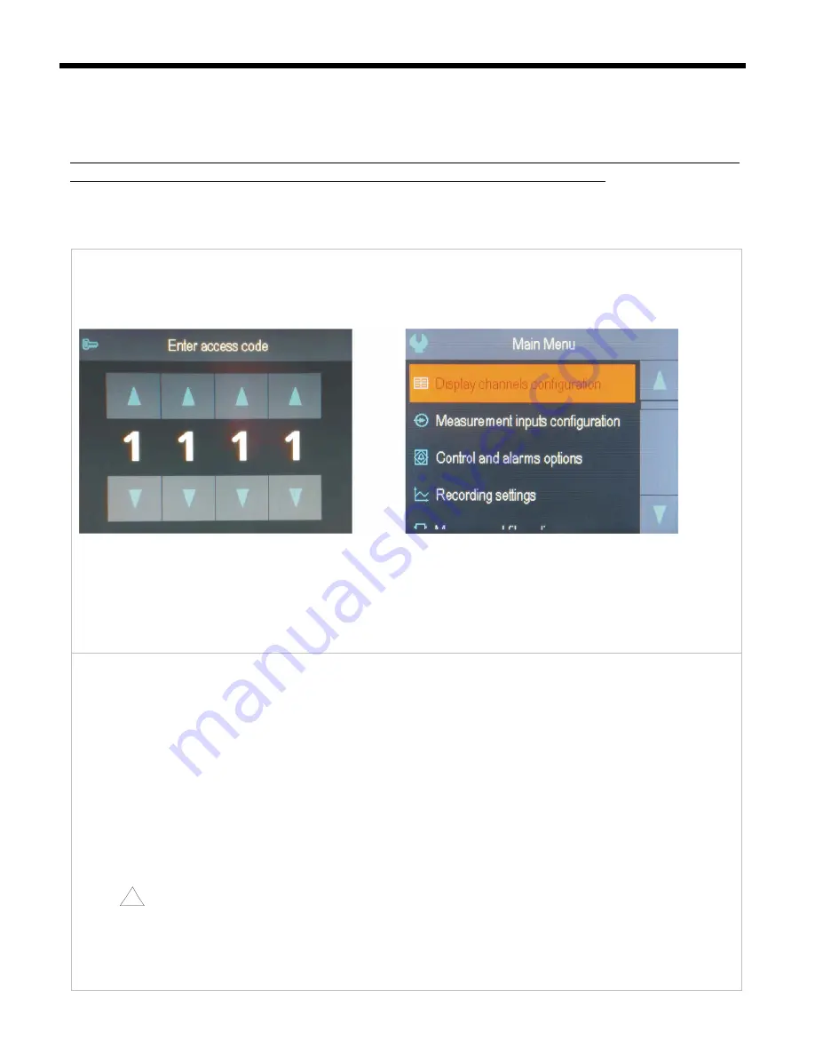
 is on, the administrator’s password must be entered - the factory-set   

   value is 

1111

, see chapter 12.9. 


Fig. 12.

 Appearance of the password screen and the 

Main Menu


- use the 

[UP]

 or 

[DOWN]

 button, or the scroll bar to select an appropriate sub-menu or parameter to be    

   changed/viewed 
- use the 

[SET]

 button or touch the selected item in the menu (also in order to edit the parameter) 

- use the 

[UP]

[DOWN], [LEFT]

, or 

[RIGHT]

 button, or the scroll bar to change the value of the edited parameter 

- approve the changed value of the parameter by pressing the 

[SET]

 button or cancel it by pressing the 

[ESC]

 button


2.

 Use the  USB or RS485 port, or the Ethernet and the ARSOFT-CFG-WZ1 software (

on-line configuration

) to:  

- connect the recorder to a computer port and start and configure the ARSOFT-CFG-WZ1 application 
- after the connection has been established, the current measured values and the internal time and date of the   
  controller are displayed; the 

[Tx/Rx]

 icon indicates the presence of transmission (lower status bar, chapter 11.1) 

- setting and viewing of the device parameters is possible in the parameter configuration window 
- new parameter values must be approved with the 

Approve changes

 button 

- the software enables synchronization of the time and the date with the computer 
- the current configuration can be saved in a file on the disk or set using values read from a file 

the recorder updates

 the configuration files and

 the displayed names after it is disconnected from the    

   computer's USB port


- online configuration via the USB port is possible only when the 

USB operation mode

 parameter is set as  


Available for computer (device)

, chapter 12.8. 

NOTE:


!


- before disconnecting the device from a computer, press the 

Disconnect device

 button 

- in the event of no response:  
- in the 

Program options

 check the configuration of the port and the 

MODBUS Address of the device

 (in the  

   case of the RS485) 

Содержание AR654

Страница 1: ...IVERSAL FOUR CHANNEL CONTROLLER WITH PROCESS RECORDING AND ATIMER Version 1 0 1 2017 03 24 APAR SALES OFFICE 05 090 Raszyn ul Ga czy skiego 6 Tel 48 22 101 27 31 48 22 853 49 30 E mail automatyka apar...

Страница 2: ...TOUCHSCREEN 10 11 DESCRIPTION OF DATA SHOWN ON THE LCD DISPLAY 12 11 1 UPPERAND LOWER DEVICE STATUS BAR 12 11 2 VIEW OFAMEASUREMENT GROUPAND CONTROL PARAMETERS CONTROL 13 11 3 VIEW OFAMEASUREMENT GRO...

Страница 3: ...MODBUS RTU TCP 37 21 USER S NOTES 40 Please pay particular attention to the text marked with this sign The manufacturer reserves the right to make changes to the design and the software firmware of t...

Страница 4: ...N to change the operating modes of the associated outputs control start stop selection of the day night setpoint value manual automatic mode for outputs the analogue outputs are logically connected to...

Страница 5: ...d transducers current output depending on the version compensation of line resistance for resistance sensors automatic or permanent compensation of thermocouple cold tip temperature automatic or perma...

Страница 6: ...e 200 620 C thermocouple E TC NiCr CuNi 25 850 C Pt1000 RTD 3 or 2 wire 200 620 C thermocouple N TC NiCrSi NiSi 35 1 300 C thermocouple J TC Fe CuNi 40 800 C current mA Rin 100 0 4 20 mA thermocouple...

Страница 7: ...B s depending on the type of the memory RS485 MODBUS RTU protocol SLAVE speed 2 4 115 2 kbit s sign format 8N1 galvanic separation Ethernet type 100base T socket RJ45 data transfer up to 135 kB s depe...

Страница 8: ...signals a measurement connections RTD TC mA V mV R INPUT1 INPUT4 the parameters configuration is described in chapter 12 3 a 1 connection of the 2 and 3 wire transducer Iou output current Uou output...

Страница 9: ...site In the Windows 7 system from the Device Manager level manual installation is performed in the following manner 1 Right click the item Apar Composite Device and select Update the driver software a...

Страница 10: ...guration display of current measurement data as well as the date and the time configuration of the real time clock RTC and other parameters such as types measurement inputs names of measurement channe...

Страница 11: ...ling the Device status screen hardware information operation and Ethernet services parameters current record number in the csv archive file etc the function is available also from the level of the F b...

Страница 12: ...ching the area of the displayed measured value PV or setpoint value SP change of the setpoint value selected with the Setpoint SP selection parameter chapter 12 4 1 limit of settings defined by parame...

Страница 13: ...iew of a measurement group text and an analogue indicator none single measurement chart Quick configuration screen for main parameters of the control channel 9 Tx Rx signalling of presence of serial t...

Страница 14: ...haracters and unit up to 4 characters of the measurement channel name and unit taken from the AR654 txt file chapter 12 2 measured value PV with signalling of exceeded measurement range chapters 12 3...

Страница 15: ...easured value PV and unit of the measurement channel chapters 11 2 and 11 3 graphic presentation of the measurement analogue indicator works in the range set by the parameters Bottom of the range for...

Страница 16: ...ter to be changed viewed use the SET button or touch the selected item in the menu also in order to edit the parameter use the UP DOWN LEFT or RIGHT button or the scroll bar to change the value of the...

Страница 17: ...eypad or on line via the computer s USB port because the changed parameter values are stored in the internal memory after the user exits the Main Menu by pressing the ESC button or disconnects the dev...

Страница 18: ...2 IN3 IN4 The smallest of the measurements IN3 and IN4 Sum of the measurements IN1 IN2 The smallest of the measurements IN1 IN2 and IN3 Sum of the measurements IN3 IN4 The smallest of IN1 IN2 IN3 IN4...

Страница 19: ...signal 0 10 V 0 60 mV voltage signal 0 60 mV 0 850 resistance signal 0 850 Line resistance 1 0 00 50 00 total resistance of leads for 2 wire RTD sensors and 850 0 00 Thermocouple cold tip temperature...

Страница 20: ...For outputs that are not related to any displayed measurement channels the Quick configuration screen chapter 11 7 is not available and the operating parameters of those outputs must be configured in...

Страница 21: ...arameters Setpoint value for the manual mode and Pulsing period for the manual mode described further in this table Setpoint value SP selection Setpoint alarm value SP1 applies to SP1 and H1 from the...

Страница 22: ...ter is insignificant chapter 12 4 1 3 5 sec Output emergency state No change status of the control alarm outputs if the measurement range of the control signal is exceeded or in the case of a failure...

Страница 23: ...ement channel is to use the Quick configuration screen chapter 11 7 As an alternative it is possible to change the setpoint values in the parameter configuration mode using the methods described in ch...

Страница 24: ...program control chapter 12 4 3 which can be useful to control the actuator elements e g heating cooling with power control or for impulse optical acoustic signalling The operation status and the setp...

Страница 25: ...nu for the selected PID set 1 8 Parameter Range of variability of the parameter and description Default settings Assigned and active outputs the numbers 1 4 or None are displayed of the control output...

Страница 26: ...location of the range of proportionality Pb in relation to the setpoint value SP for heating parameter Control type Reverse heating b location of the range of proportionality Pb in relation to the se...

Страница 27: ...used buttons or BIN inputs The power supply must be switched on immediately after the tuning is started in the output switch on delay phase If the power supply is switched on later an erroneous analy...

Страница 28: ...2 and in the Quick configuration screen the status of operation of the program is shown in the line starting with the phrase PRGx where x is the number of the program the meaning of the individual fie...

Страница 29: ...and the Pulsing period taken from the parameters of the associated auxiliary output chapter and table 12 4 1 Sound signal Disabled signalling of the duration of the section with a built in acoustic tr...

Страница 30: ...active within the range of the Time defined by the parameters Start and End of time limit Above the permission threshold recording is active when the measured value defined by the Selection of permis...

Страница 31: ...ected or the internal memory when there is no USB memory Identification number ID 0 999 an individual device number entered into the initial records in the archive file csv in order to distinguish arc...

Страница 32: ...e names as well as access to the archive files with the exception of the RS485 Moreover the Ethernet enables displaying information on the operating status and on measurements of the controller in any...

Страница 33: ...hout a fixed public IP address an active account in a DDNS service is required the description can be found in chapter 12 8 1 Disabled Enabled Dynamic DNS settings and status Configuration data and st...

Страница 34: ...ary unavailability of the service or permanent nature which indicates inadequate Internet connection improper configuration of the connection or service codes 2 to 12 e g DDNS 5 means invalid username...

Страница 35: ...switched on the control status is exactly the same as at the time of switching off the power supply no change chapter 12 6 Touch panel lock touch screen and keypad lock except for F BIN5 input functi...

Страница 36: ...tes text files with the csv extension in the internal memory or the USB memory Additional new csv files are created each time the power supply is switched on and each time a new recording is started e...

Страница 37: ...disk operations being performed In order to close the message window appearing in the display use the SET or ESC button Fig 15 Appearance of an example message window 16 IMPORTANT COMMENTS PERTAINING...

Страница 38: ...both ends of the line 150 each between lines Equipment from different manufacturers that form the RS485 network e g RS485 converters USB may have integrated polarizing and terminating resistors in su...

Страница 39: ...unctions READ 3 or 4 WRITE 6 Table 19 1 Request frame format of the MODBUS TCP protocol for the READ and WRITE functions frame length 12B Heading of the MODBUS protocol 7 bytes Function code READ or W...

Страница 40: ...reserved R 0x42 66 0x0101 0x630C years HB and months LB Parameter Start of the time limit chapter 12 5 R W 0x43 67 0x0100 0x1F17 days HB and hours LB R W 0x44 68 0x0000 0x3B3B minutes HB and seconds...

Страница 41: ...2 Parameter State of control after power up R W 0xAA WY 32 0 2 Parameter Control time R W 0xAB WY 32 0x0101 0x630C years HB and months LB Parameter Start of control time R W 0xAC WY 32 0x0100 0x1F17...

Страница 42: ...R W 0x14E 334 0x0000 0xFFFF Octet2 HB Octet1 LB 0x14F 335 0x0000 0xFFFF Octet4 HB Octet3 LB Parameter Default gateway chapter 12 8 R W 0x150 336 0x0000 0xFFFF Octet2 HB Octet1 LB 0x151 337 0x0000 0xFF...

Отзывы: