background image

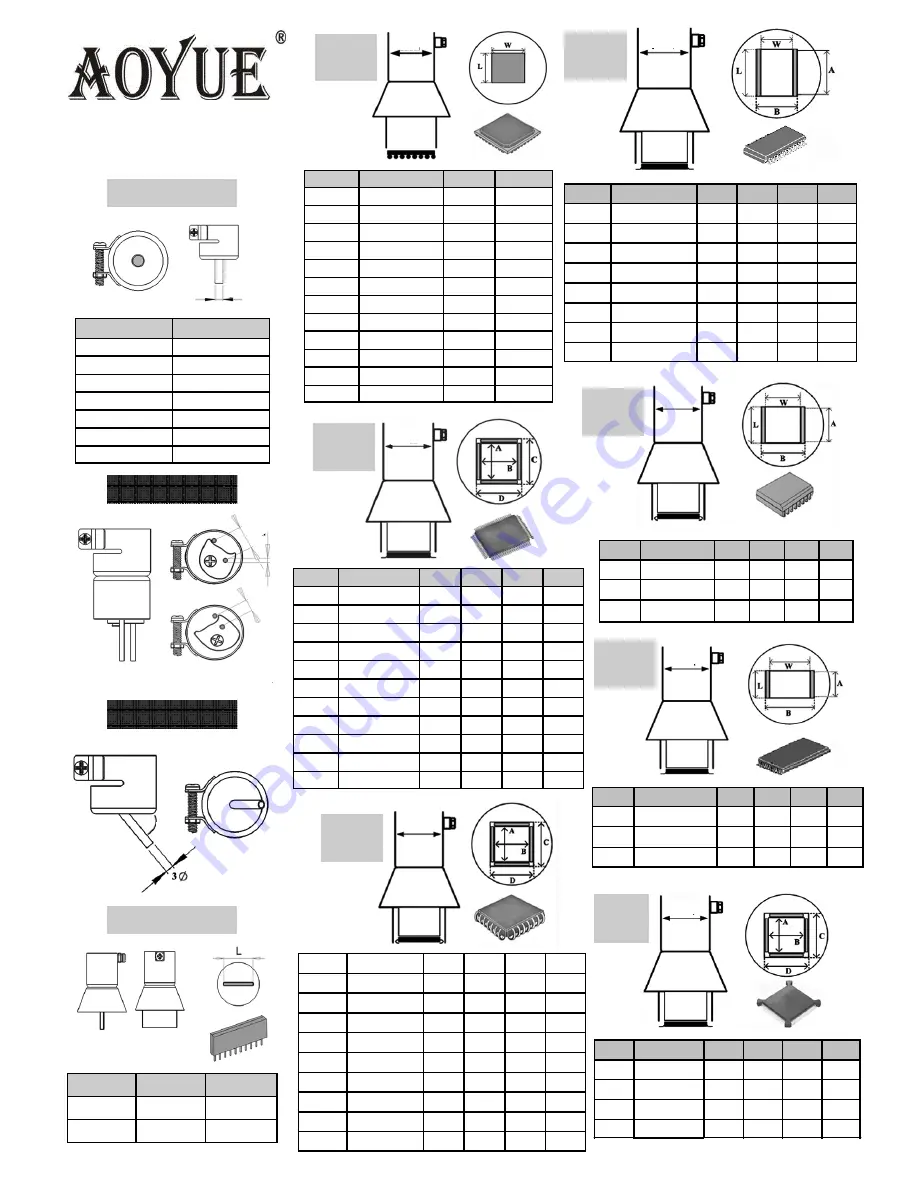
Replacement Air 

Nozzles


1325


Air Nozzle


1142 

Air Nozzle


MODEL


NOZZLE SIZE 

Ø


1124 

2.4mm 

1130 

4.4mm 

1194 

6mm 

1195 

8mm 

1196 

7mm 

1197 

9mm 

1198 

12mm 

MODEL


IC SIZE 

L(mm) 

1191 

SIP25L 

26 

1192 

SIP50L 

52.5 

MODEL


IC SIZE 

L(mm) 

W(mm) 

1010 

9×9mm 

10 

10 

1313 

12×12mm 

13 

13 

1616 

15×15mm 

16 

16 

1919 

18×18mm 

19 

19 

2828N 

27×27mm 

28 

28 

3030N 

29×29mm 

30 

30 

3232W 

31×31mm 

32 

32 

3636W 

36×36mm 

36 

36 

3939W 

38×38mm 

39 

39 

4141W 

40×40mm 

41 

41 

4343W 

42×42mm 

43 

43 

4545W 

44×44mm 

45 

45 

MODEL


IC SIZE 

A(mm) 

B(mm) 

C(mm) 

D(mm) 

1125 

10×10mm 

16 

16 

1126 

14×14mm 

14 

14 

21 

21 

1127  17.5×17.5mm 

18 

18 

25 

25 

1128 

14×20mm 

20 

14 

21 

27 

1129 

28×28mm 

28 

28 

35 

35 

1215  42.5×42.5mm 

41 

41 

48 

48 

1261 

20×20mm 

19 

19 

26 

26 

1262 

12×12mm 

11 

11 

18 

18 

1263 

28×40mm 

38 

28 

35 

45 

1264 

40×40mm 

39 

39 

46 

46 

1265 

32×32mm 

31 

31 

38 

38 

MODEL


IC SIZE 

L(mm) 

W(mm) 

A(mm)  B(mm) 

1131 

4.4×10mm 

11 

3.8 

10.3 

1132 

5.6×13mm 

16 

4.7 

14 

11.7 

1133 

7.5×15mm 

17 

15 

13 

1134 

7.5×18mm 

20 

18 

13 

1257 

11×21mm 

22 

11 

20 

18 

1258 

7.6×12.7mm 

12 

10 

14 

1259 

13×28mm 

30 

12.5 

28 

19.5 

1260 

8.6×18mm 

20 

7.7 

18 

14.7 

MODEL


IC SIZE 

L(mm)  W(mm)  A(mm)  B(mm) 

1183 

15×8mm 

17 

15 

14 

1184 

18×8mm 

20 

18 

16 

1214 

10×26mm 

27 

11 

25 

18 

TSOL


SERIES


MODEL


IC SIZE 

L(mm)  W(mm)  A(mm)  B(mm) 

1185 

13×10mm 

11 

11 

18 

1186 

18×10mm 

12 

17 

10 

24 

1187 

18.5×8mm 

11 

18 

25 

MODEL


IC SIZE 

L(mm)  W(mm)  A(mm)  B(mm) 

1180 

17×17mm 

17.2  17.2  24.2  24.2 

1181 

19×19mm 

18.2  18.2  25.2  25.2 

1182 

24×24mm 

23.2  23.2  30.2  30.2 

1203 

35×35mm 

34.2  34.2  41.2  41.2 

BQFP 

SE-

SGL


SERIES


SIL


SERIES


45

º 

10

mm


5mm


22mm


22mm


22mm


22mm


22mm


22mm


22mm


SOJ


SERIES


SOP


SERIES


BGA


SERIES


QFP


SERIES


PLCC


SERIES


Ø 

MODEL


IC SIZE 

A(mm) 

B(mm) 

C(mm) 

D(mm) 

1135  17.5×17.5mm  17.5  17.5  24.5  24.5 

1136 

20×20mm 

20 

20 

27 

27 

1137 

25×25mm 

25 

25 

32 

32 

1138 

30×30mm 

30 

30 

37 

37 

1139  7.3×12.5mm  7.5 

12.5  14.5  19.5 

1140  11.5×11.5mm  12 

12 

19 

19 

1141 

11.5×14mm 

12 

14 

19 

21 

1188 

9×9mm 

10 

10 

17 

17 

1189 

34×34mm 

35.5  35.5  42.5  42.5 

Содержание Int968

Страница 1: ...u for purchasing Aoyue Int968 Repairing System It is important to read the manual before using the equipment Please keep manual in accessible place for future reference Deluxe Repairing System Centigr...

Страница 2: ...Assembly and Preparation 8 Operating Guidelines 9 17 Care and Maintenance 18 Basic Troubleshooting Guide 19 Air Nozzles 20 This manual is designed to familiarize and instruct the op erator with the p...

Страница 3: ...ackage It has several safety features such as the auto cooling process of the Hot Air Gun and overheat protection circuit It has several advanced features such as Centigrade and Fahrenheit display sel...

Страница 4: ...mes created at the source Knob type Soldering Iron temperature control for simple yet efficient working temperature selection Solder Iron digital calibration Easily adjust temperature offset with a fe...

Страница 5: ...C Heating Element Ceramic Heater Output Voltage 24V Tip to Ground Resistance Below 2 Tip to Ground Potential Below 2mV HOT AIR Power Consumption 550W Temperature Range 100 C 480 C Heating Element Cera...

Страница 6: ...p or sharply jolt the unit Contains delicate parts that may break if unit is dropped Unplug the unit from the main power source if it will not be used for a long period Turn off power during breaks if...

Страница 7: ...bsorber function switch B1 Hot Air Gun temperature display B2 Hot Air Gun decrease temperature adjustment button B3 Hot Air Gun increase temperature adjustment button B4 Hot Air Gun activation switch...

Страница 8: ...ce the soldering iron to the soldering iron stand 4 Attach soldering iron spring holder as seen 5 C Soldering Iron Stand D Hot Air Gun The Hot Air Gun holder was installed on the station upside down f...

Страница 9: ...ns properly secured switch ON the device by activating the main power switch 3 The display panel B1 will temporarily show the product name in a scrolling manner and then display OFF once the scroll is...

Страница 10: ...te after the desired hot air temperature and airflow level are reached as also indicated from display panel B1 and the airflow gauge 7 When reworking is complete return the Hot Air Gun to its holder a...

Страница 11: ...heater indicator LED indicates desired temperature is reached 5 When soldering is complete deactivate the SOLDER IRON activation switch A4 It is now safe to switch off the main power switch H System S...

Страница 12: ...ocedures 1 to 6 2 Adjust system selection menu to Sel 2 then press the hot air gun increase temperature adjustment button B3 3 If successful the display B1 would show t30 indicating Hot air gun sleep...

Страница 13: ...he centigrade scale or the Fahrenheit scale To switch between the two scales follow these procedures 1 Follow System Setting procedures 1 to 6 Adjust system selection menu to 3 then press the hot air...

Страница 14: ...llow System Setting procedures 1 to 6 Adjust system selection menu to 4 then press the hot air gun increase temperature adjustment button B3 6 If successful the display B1 would show 000 indicating so...

Страница 15: ...air gun increase temperature adjustment button B3 2 If successful the display would show 000 indicating hot air gun digital calibration is being set 3 A lighted Soldering Iron heater indicator LED A1...

Страница 16: ...adjustment menu by pressing the soldering iron function switch A4 O Calibrating the Airflow If the airflow is too low or too high due to different line voltages The airflow calibration can be digital...

Страница 17: ...ibration adjustment menu by pressing the soldering iron function switch A3 5 Turn on the hot air gun function and check if additional air flow calibration is needed Repeat steps 1 to 7 each time selec...

Страница 18: ...heating element is found in the middle part of the hot air gun The normal life of a heating element is 1 year under normal operating conditions Steps 1 Loosen the 3 screws that secure the handle 2 Sli...

Страница 19: ...if the 4 screws that hold the pump in place are properly and tightly connected Unplug the system from the main power source before opening the case to check inside the station PROBLEM 5 THE UNIT IS VE...

Страница 20: ...3 8 9 10 3 1132 5 6 13mm 16 4 7 14 11 7 1133 7 5 15mm 17 6 15 13 1134 7 5 18mm 20 6 18 13 1257 11 21mm 22 11 20 18 1258 7 6 12 7mm 12 7 10 14 1259 13 28mm 30 12 5 28 19 5 1260 8 6 18mm 20 7 7 18 14 7...

Отзывы:

Похожие инструкции для Int968