


Primary
Master (1st)
Primary
Slave (2nd)
Pin 1
This motherboard comes with a 20-pin and 4-pin ATX power connector as shown
above. Make sure you plug in the right direction. We strongly recommend you to
insert the 4-pin connector before connecting the 20-pin connector.
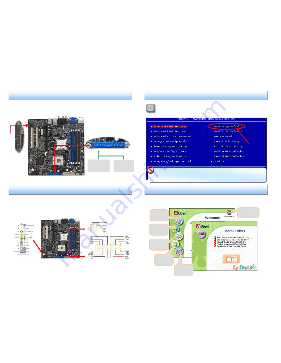
After you finish the setting of jumpers and connect correct cables. Power
on and enter the BIOS Setup, press <Del> during POST (Power On Self
Test).
Choose "Load Setup Defaults" for recommended optimal
performance.
Connect 34-pin floppy cable and 40-pin, 80-wire IDE cable to floppy connector FDD
and IDE connector. Be careful of the pin1 orientation. Wrong orientation may cause
system damage.
Pin 1
ATA 33/66/100
IDE Connector
IDE 1 (Primary)
FDD Connector
5. Connecting IDE and Floppy Cables
6. Connecting Front Panel cable and ATX Power Cables
Attach the power LED, speaker, and reset switch connectors to the corresponding
pins. If you enable “Suspend Mode” item in BIOS Setup, the ACPI & Power LED
will keep flashing while the system is in suspend mode.
Locate the power switch cable from your ATX housing. It is 2-pin female
connector from the housing front panel. Plug this connector to the soft-power
switch connector marked
SPWR.
7. Power-on and Loading BIOS Setup
Del
8. AOpen EzInstall and Bonus Pack CD
You can use the autorun menu of Bonus CD disc. Choose the utility and driver
from the icons at left side, and then click on the “
GO
” button to complete
installation automatically.
Warning
: Please avoid of using "Load Turbo Defaults", unless you are sure your
system components (CPU, RAM, HDD, etc.) are good enough for turbo setting.
Click to install
online manual
Install utility
Browse
Read me
Exit CD
Install driver


